
Liquid-evaporation-type heat radiator and manufacturing method thereof

A technology of liquid evaporation and production method, which is applied in indirect heat exchangers, heat exchange equipment, lighting and heating equipment, etc., and can solve the problems of difficult heat transfer medium to play a role, difficult heat dissipation of radiator, poor heat dissipation effect of radiator, etc. , to achieve the effect of light weight, small mass and good heat dissipation effect

Inactive Publication Date: 2012-02-08
陈志明 +2
View PDF7 Cites 9 Cited by
  • Summary
  • Abstract
  • Description
  • Claims
  • Application Information

AI Technical Summary

Problems solved by technology

[0002] At present, the air-cooled radiators in the prior art or the air-cooled radiators filled with heat-conducting medium (or cooling medium) generally fix the heat sink on the heat-conducting block used to conduct the temperature of the heating object. The radiator of this structure Because the heat sink and the heat conduction block are made as one, although it has the advantage of fast heat conduction, it is cooled by the outside air, and the heat conduction block is generally large in size and heavy in weight, so there is a large thermal inertia. In addition, if it is integrated with the heat sink, its thermal inertia will be greater, and it will be difficult for the heat of the entire radiator to dissipate into the air, even if a heat conduction medium (or cooling medium) is added to the heat sink of this structure , the heat conduction medium (or cooling medium) is also difficult to play a role, so the existing radiators generally have the disadvantages of poor heat dissipation, large volume, and heavy weight

Method used


Image

  • Liquid-evaporation-type heat radiator and manufacturing method thereof
  • Liquid-evaporation-type heat radiator and manufacturing method thereof
  • Liquid-evaporation-type heat radiator and manufacturing method thereof

Examples


Embodiment Construction

[0019] The present invention will be described in further detail below in conjunction with the accompanying drawings and embodiments.

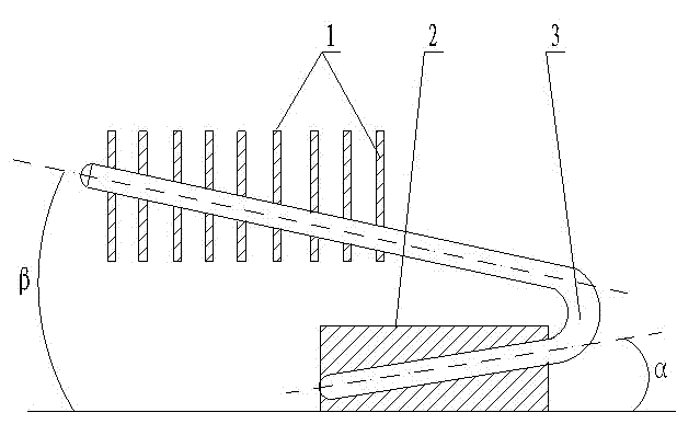
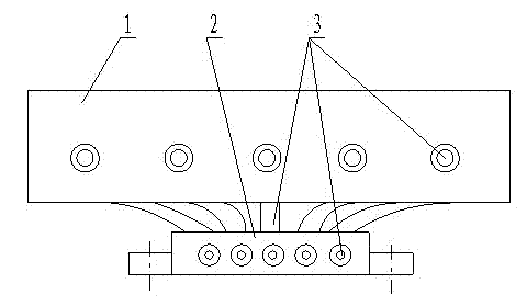
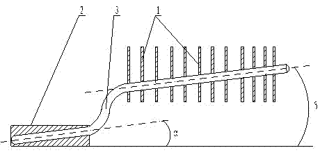
[0020] Embodiment of the present invention: when adopting the manufacturing method of a kind of liquid evaporative heat sink of the present invention to carry out manufacture, its radiator fin, heat conduction block and heat conduction tube are all made of metal material, and its metal material preferably adopts the prior art Copper, iron, aluminum or aluminum alloy materials; during production, the heat sink is separated from the heat conduction block used to conduct the temperature of the heating object, and a heat conduction pipe is set in the heat conduction block at the same time, so that a section of the heat conduction pipe is embedded in the heat conduction block , so that the other section of the heat conduction pipe protrudes from the heat conduction block and is higher than the top of the heat conduction block, the closed cavity of t...


PUM


Abstract

The invention discloses a manufacturing method of a liquid-evaporation-type heat radiator. The method provided by the invention comprises the following steps: setting a heat radiation plate and a heat conduction block which conducts the temperature of objects emitting heat to be separated; simultaneously arranging a heat conduction pipeline in the heat conduction block, wherein one section of the heat conduction pipeline is embedded in the heat conduction block, and the other section of the heat conduction pipeline extends out of the heat conduction block and is higher than the top end of the heat conduction block; adding and pouring liquids which can be evaporated into the enclosed containing chamber of the heat conduction pipeline; and then mounting the heat radiation plate on the heat conduction pipeline which is higher than the top end of the heat conduction block. According to the invention, the temperature of the objects emitting heat is utilized for heating the liquids which can be evaporated in the heat conduction pipeline, thus the liquids which can be evaporated are heated rapidly into evaporation gases and radiate through the heat radiation plate, and after the evaporation gases are changed into liquids which can be evaporated after the evaporation gases are cooled, and flow back to the lower part of the heat conduction pipeline for the next evaporation and heat transfer circulation. The method provided by the invention has the advantages of good heat radiation effect, small volume, lighter weight, easiness in manufacturing, lower manufacturing cost and the like.

Description

technical field [0001] The invention relates to a liquid evaporative radiator and a manufacturing method thereof, belonging to the technical field of air-cooled radiator manufacturing. Background technique [0002] At present, the air-cooled radiators in the prior art or the air-cooled radiators filled with heat-conducting medium (or cooling medium) generally fix the heat sink on the heat-conducting block used to conduct the temperature of the heating object. The radiator of this structure Because the heat sink and the heat conduction block are made as one, although it has the advantage of fast heat conduction, it is cooled by the outside air, and the heat conduction block is generally large in size and heavy in weight, so there is a large thermal inertia. In addition, if it is integrated with the heat sink, its thermal inertia will be greater, and it will be difficult for the heat of the entire radiator to dissipate into the air, even if a heat conduction medium (or cooling...

Claims


Application Information

Patent Timeline
IPC IPC(8): F28D15/02F28F21/08
Inventor 陈志明顾伟
Owner 陈志明
Learn More