Charge pump

A charge pump and capacitor technology, applied in the field of charge pump with high charge conversion efficiency, can solve the problem that the charge pump cannot be integrated into the chip

Active Publication Date: 2014-09-24
ACER INC
View PDF6 Cites 0 Cited by
  • Summary
  • Abstract
  • Description
  • Claims
  • Application Information

AI Technical Summary

Problems solved by technology

[0008] The purpose of the present invention is to overcome the defects of the existing charge pump and provide a new type of charge pump. The technical problem to be solved is to solve the problem that the charge pump of the prior art cannot be integrated on the chip. very practical

Method used


Image

  • Charge pump
  • Charge pump
  • Charge pump

Examples


Embodiment Construction

[0066] In order to further explain the technical means and effects of the present invention to achieve the intended purpose of the invention, the specific implementation, structure, characteristics and effects of the charge pump proposed according to the present invention will be described below in conjunction with the accompanying drawings and preferred embodiments. Details are as follows.

[0067] The aforementioned and other technical contents, features and effects of the present invention will be clearly presented in the following detailed description of preferred embodiments with reference to the drawings. For convenience of description, in the following embodiments, the same elements are denoted by the same numbers.

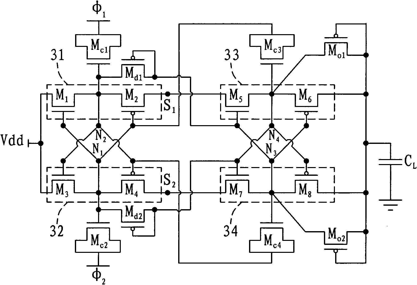
[0068] see image 3 , is a schematic diagram of the first embodiment of the charge pump of the present invention. In the figure, the charge pump includes a first stacking portion 31, a second stacking portion 32, a third stacking portion 33, a fourth stac...


PUM


Abstract

The invention relates to a charge pump. The charge pump can amplify an input voltage which is received at an input end and output the amplified output voltage at an output end. The charge pump comprises a plurality of transistors of which sources and drains are coupled, a plurality of overlapped transistors and a plurality of diode connection type transistors, wherein the transistors of which the sources and the drains are coupled serve as charging capacitors; the overlapped transistors are connected between the input end and the output end in a symmetric arrangement mode; and the diode connection type transistors are used for preventing the transistors of which the sources and the drains are coupled from being broken down in a charge transfer process and improving a charge transfer speed. The charge pump can be integrated on a chip by replacing the charging capacitors with the transistors of which the sources and the drains are coupled; and the problem of breakdown of the transistors can be solved by arranging the diode connection type transistors in the charge pump.

Description

technical field [0001] The invention relates to a charge pump, in particular to a charge pump with high charge conversion efficiency. Background technique [0002] At present, the charge pump is usually used as a booster circuit (Booster) or a voltage multiplier circuit (Voltage Multiplier), which increases the input voltage provided by the low voltage source to a higher potential working voltage to provide various needs. High voltage drive circuit. [0003] see figure 1 , is a schematic diagram of a Dickson charge pump in the prior art. In the figure, the Dickson charge pump includes four switches SW1-SW4 (not shown in the figure), four charging capacitors C1-C4, an output capacitor Cout and five N-type metal oxide semiconductor transistors with source-drain coupling T1-T5. The potentials of the input terminal and the output terminal of the Dickson charge pump are represented by Vin and Vout, respectively. And the charging capacitors C1-C4 are used to respectively rece...

Claims


Application Information

Patent Timeline
Patent Type & Authority Patents(China)
IPC IPC(8): H02M3/07
Inventor 吴俊毅谢维致张铭宏黄威
Owner ACER INC
Why Eureka
Try Eureka