Workpiece clamp for numerical control machine tool

A technology of CNC machine tools and workpiece fixtures, which is applied in the direction of manufacturing tools, metal processing machinery parts, clamping, etc., can solve the problems that affect the processing efficiency of CNC machine tools and the high frequency of tool change of CNC machine tools, and achieve reduced time, low tool change frequency, and The effect of improving processing efficiency

Inactive Publication Date: 2012-02-15
SHANGHAI HUIYI CONTROL SYST
View PDF8 Cites 10 Cited by
  • Summary
  • Abstract
  • Description
  • Claims
  • Application Information

AI Technical Summary

Problems solved by technology

The existing fixtures for fixing workpieces of CNC machine tools all use bench vises or suction cups. This kind of fixtures can only clamp one workpiece at a time, so there are the following defects in batch processing: 1) Each workpiece needs to be clamped once ;2) Since only one workpiece can be processed at a time, the tool change frequency of CNC machine tools is very high
The above defects affect the processing efficiency of CNC machine tools in batch processing

Method used


Image

  • Workpiece clamp for numerical control machine tool
  • Workpiece clamp for numerical control machine tool
  • Workpiece clamp for numerical control machine tool

Examples


Embodiment Construction

[0016] The embodiments of the present invention will be described in further detail below in conjunction with the accompanying drawings, but the present embodiments are not intended to limit the present invention, and any similar structures and similar changes of the present invention should be included in the protection scope of the present invention.

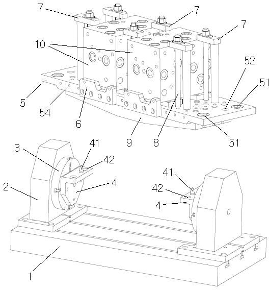
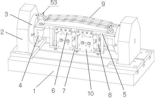
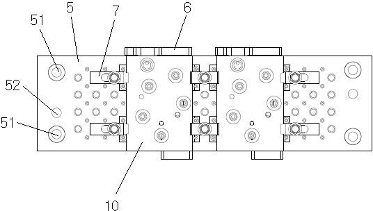
[0017] Such as Figure 1-Figure 3 As shown, a workpiece fixture for a numerically controlled machine tool provided by an embodiment of the present invention, the numerically controlled machine tool includes a workbench 1, and a power seat 2 mounted on the workbench 1 on the left and right and slides linearly along the same axis, and two A rotating power head 3 is respectively arranged on the power base 2, and the rotation axes of the two power heads 3 coincide. The two power bases 2 are respectively the main power base and the slave power base. The two power heads 3 are respectively The main power head and the slave power head...


PUM


Abstract

The invention discloses a workpiece clamp for a numerical control machine tool, which relates to the technical field of numerical control machine tools and aims at solving the technical problem of improving the batch processing efficiency. The clamp comprises two transfer plates, a bridge plate, a plurality of side screw bolts, a plurality of side pressing plates, a plurality of positioning screw rods, a plurality of positioning pressing plates and four ball lock shafts, wherein the two transfer plates are respectively arranged on two motive power heads of the numerical control machine tool, the upper part of each transfer plate is respectively bent in the direction towards the other transfer plate and is respectively provided with an initial positioning pin, the front part and the back part of each transfer plate are respectively provided with a transfer hole, a ball lock is arranged in each transfer hole, the bridge plate is a rectangular flat plate, screw hole arrays are arranged on the plate surface of the bridge plate, an initial positioning hole is respectively arranged at the left edge and the right edge of the plate surface of the bridge plate, four bridging holes are arranged at four corners of the plate surface of the bridge plate, a plurality of side screw holes are respectively arranged at the peripheral surface of each long edge of the bridge plate, the plate surface of each side pressing plate is provided with a plurality of side pressing holes, and positioning holes for the positioning screw rods to pass through are respectively arranged on each positioning pressing plate. The clamp provided by the invention can be used for mounting and clamping a plurality of workpieces in one step.

Description

technical field [0001] The invention relates to the technology of numerical control machine tools, in particular to the technology of workpiece fixtures of numerical control machine tools. Background technique [0002] The working table of the CNC machine tool is equipped with two power seats that slide linearly along the same axis, and a rotating power head is provided on each of the two power seats. Rotating workpiece control mechanism. When the CNC machine tool is cutting and processing the workpiece, the workpiece is first fixed on the power head, and then the workpiece control mechanism is used to control the sliding of the power seat and the rotation of the power head, so that the workpiece slides or rotates on the worktable to match the cutting of the tool. The existing fixtures for fixing workpieces of CNC machine tools all use bench vises or suction cups. This kind of fixtures can only clamp one workpiece at a time, so there are the following defects in batch proce...

Claims


Application Information

Patent Timeline
Patent Type & Authority Applications(China)
IPC IPC(8): B23Q3/06
Inventor 王宏圣
Owner SHANGHAI HUIYI CONTROL SYST
Why Eureka
Try Eureka