Wing folding mechanism suitable for folding wing at any angle

A technology of wing folding mechanism and arbitrary angle, which is applied in the direction of wing adjustment, etc., can solve the problems of easy aging of materials, low-speed performance, low strength, low stiffness, and instability of inflatable folding wings, and achieve low launch site requirements and launch The process is simple and fast, and the effect of convenient storage and transportation

Inactive Publication Date: 2012-02-15
HARBIN INST OF TECH
View PDF6 Cites 16 Cited by
  • Summary
  • Abstract
  • Description
  • Claims
  • Application Information

AI Technical Summary

Problems solved by technology

[0004] The purpose of the present invention is to provide a wing folding mechanism suitable for folding wings at any angle, so as to solve the problem that the current rigid folding wings cannot meet the high requirements for low-speed performance and have relatively high impact on the flatness of the wings of the aircraft. High requirements and inflatable folding wings have low strength and stiffness, and are easy to lose stability under bending moments; the problem of easy aging of materials

Method used


Image

  • Wing folding mechanism suitable for folding wing at any angle
  • Wing folding mechanism suitable for folding wing at any angle
  • Wing folding mechanism suitable for folding wing at any angle

Examples


specific Embodiment approach 1

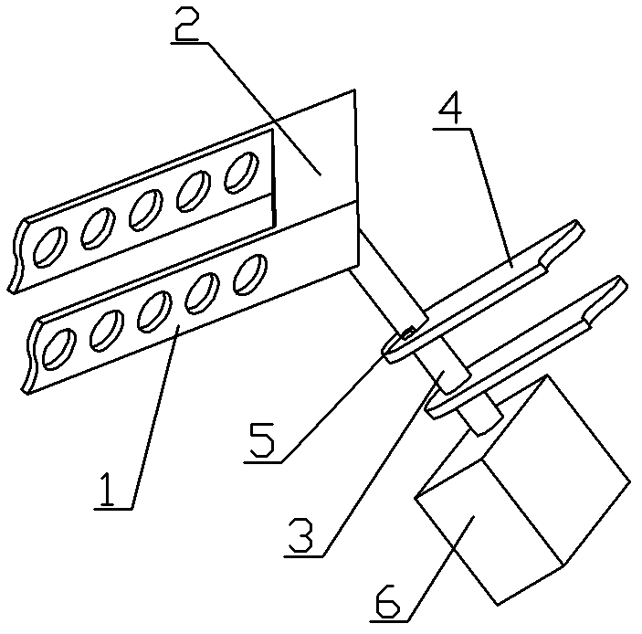
[0012] Specific implementation mode one: combine image 3 and Figure 4 Describe this embodiment, the described mechanism of this embodiment comprises wing spar 1, wing mounting frame 2, rotating shaft 3, rotating shaft mounting seat 4, locking device 5 and deployment actuating device 6, and wing spar 1 is installed on the wing On the mounting frame 2, one end of the rotating shaft 3 is fixed to the wing mounting frame 2, and the other end of the rotating shaft 3 passes through the rotating shaft mounting seat 4 and is connected to the unfolding actuating device 6, and the rotating shaft 3 is rotationally connected to the rotating shaft mounting seat 4, and the rotating shaft is installed A locking device 5 for locking the rotating shaft is installed on the seat 4, which is characterized in that the direction along the fuselage axis and pointing to the front of the aircraft is the positive direction of the x-axis, and the direction along the line connecting the wingtips of the...

specific Embodiment approach 2

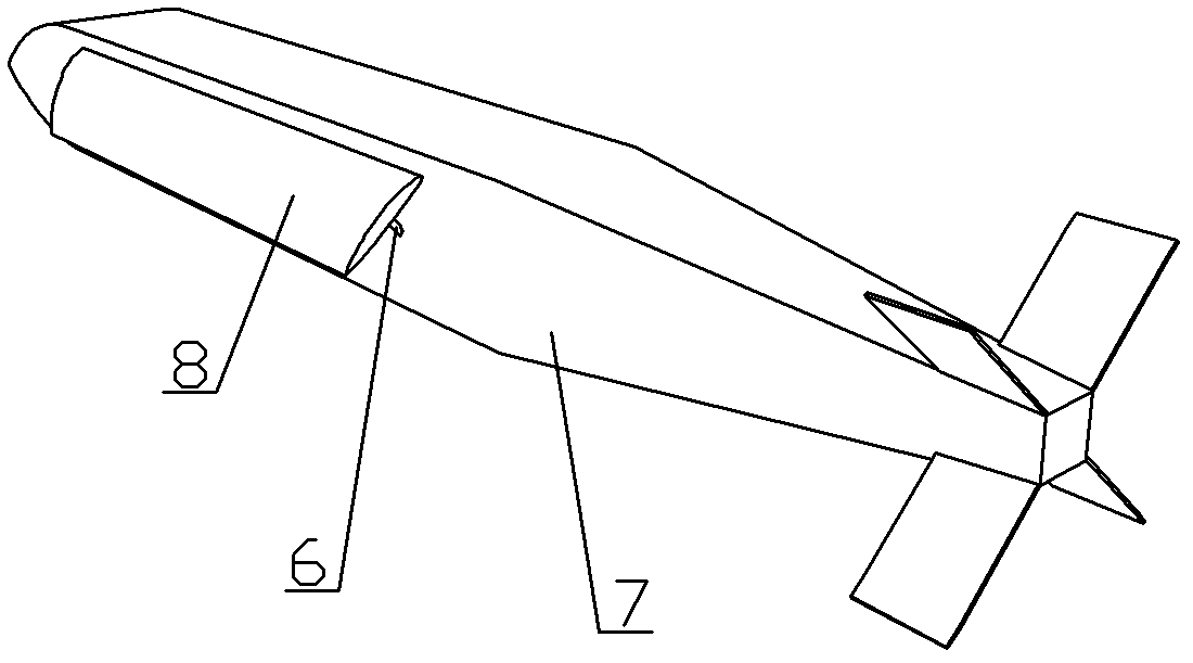
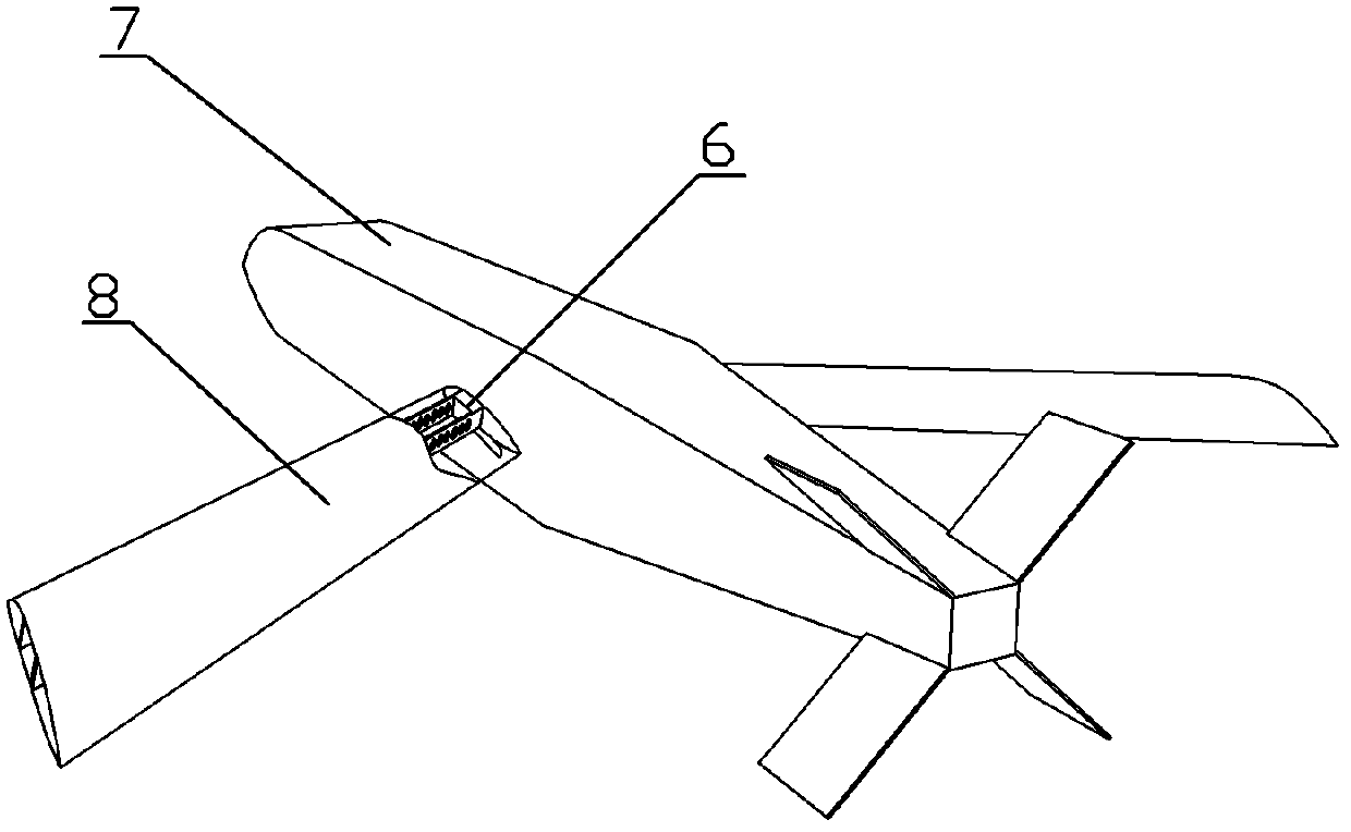
[0017] Specific implementation mode two: combination figure 2 Describe this embodiment, the dihedral angle η of this embodiment is 3°, the sweep angle β is 0° and the installation angle When it is 2°, the direction vector of the rotation axis 3 in the space Cartesian coordinate system in which the flight direction of the aircraft is the negative direction of the x-axis and the vertical upward direction is the positive direction of the z-axis is (-105.1, 99.7, 108.8). This structure is suitable for A low-speed, straight-winged aircraft. Other components and connections are the same as those in the first embodiment.

specific Embodiment approach 3

[0018] Specific implementation mode three: combination figure 2 Describe this embodiment, the dihedral angle η of this embodiment is 0°, the sweep angle β is 50° and the installation angle When the rotation axis 3 is 1°, the direction along the axis of the fuselage and pointing to the front of the aircraft is the positive direction of the x-axis, and the direction along the line connecting the wingtips of the two wings and pointing to the left side of the aircraft is the spatial rectangular coordinate of the positive direction of the y-axis. The direction vector in the system is (35.6, 100.0, 100.6), and this structure is suitable for aircraft with medium speed and slight sweep angle. Other components and connections are the same as those in the first embodiment.


PUM


Abstract

The invention discloses a wing folding mechanism suitable for folding a wing at any angle, relates to a wing folding mechanism, and aims to solve the problems that a rigid folding wing cannot meet the high requirements on low speed performance of an aircraft and flatness of the wing of the aircraft, an inflatable folding wing has low strength and rigidity and is easily instable under bending moment, and materials are easy to age at present. In a space rectangular coordinate system taking a direction which is along the axis of an aircraft body and points to front of the aircraft as an x axis positive direction and a direction which is along a connecting line of wing tips of two wings and points to the left side of the aircraft as a y axis positive direction, the direction vector of a rotating shaft and the rotation angle of a wing installation frame around the axis of the rotating shaft are shown in the specifications. The wing folding mechanism is used for an unmanned aerial vehicle.

Description

technical field [0001] The invention relates to a wing folding mechanism. Background technique [0002] In military operations, if there is a drone that can respond quickly, launch in a short time, and conduct close-range detection and attack on the target, it will help to grasp the fighter, thereby greatly reducing combat losses; in search and rescue work Among them, the speed and accuracy of obtaining information are also emphasized. In the fields of civil and scientific research, efficiency is also crucial. Therefore, there is an urgent need for an unmanned aerial vehicle system that is convenient for storage and transportation, and simple and quick for launch and recovery. [0003] Existing drones are usually designed to be detachable and need to be assembled before launch, which takes a long time to launch. There are also a few folding unmanned aerial vehicles, such as the American "Quicklook" howitzer-launched drone, artillery-launched wide-area reconnaissance projec...

Claims


Application Information

Patent Timeline
Patent Type & Authority Applications(China)
IPC IPC(8): B64C3/56
Inventor 武睿阿其图
Owner HARBIN INST OF TECH
Why Eureka
Try Eureka