Plasma nanometer bubble generator

A technology of nano-bubbles and generators, applied in water aeration, sustainable biological treatment, chemical instruments and methods, etc., to achieve the effects of small bubble diameter, high internal energy, and high oxygen utilization

Active Publication Date: 2013-06-05
江苏金禾水环境科技股份有限公司
View PDF3 Cites 0 Cited by
  • Summary
  • Abstract
  • Description
  • Claims
  • Application Information

AI Technical Summary

Problems solved by technology

[0004] In order to solve the defects of large bubbles, high energy consumption, short transmission distance and low oxygen utilization rate in the prior art, the invention provides a plasma nano-bubble generator , effectively overcome the shortcomings of the existing technology

Method used


Image

  • Plasma nanometer bubble generator

Examples


Embodiment Construction

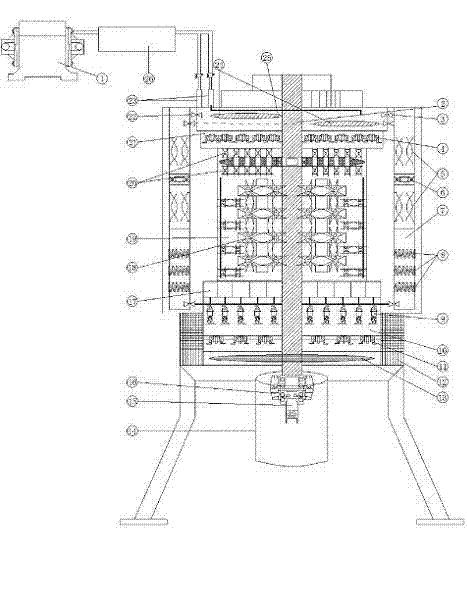
[0018] The air is pressurized by the air pump 1 and enters the gas ionization device 26, and the ionized gas enters the balance chamber 25 through the air inlet 23, and the water entering through the water inlet 3 and the water inlet 22 in the balance chamber is separated by the drive shaft. 2. The effects of the driven balance plate 24 and the balance assembly 4 reach an overbalanced state. In the super-balanced state, the gas-water flow enters the balance guide chamber 21 under the pressure of the air pump 1, and enters the disturbance chamber 19 through the balance guide assembly 20. In the disturbance chamber, the disturbance assembly 18 performs 4-stage balance disturbance to generate fine bubbles and then enters the bubble liquid. Disperse waterway 17.

[0019] When excessive pressure is generated in the balance chamber, the gas is introduced into the bypass pressure divider chamber 7 on both sides, and enters the balance component 9 after the pressure is buffered by the...


PUM


Abstract

The invention discloses a plasma nanometer bubble generator which comprises a gas ionization unit, a gas-liquid balance chamber, a gas-liquid agitating chamber, partial pressure units, a gas-liquid injection chamber and a variable-speed driving unit, wherein the gas ionization unit is connected with the gas-liquid balance chamber; the gas-liquid balance chamber, the gas-liquid agitating chamber and the gas-liquid injection chamber are connected from the top to the bottom in sequence; the gas-liquid balance chamber and the gas-liquid injection chamber are respectively connected with the partial pressure units at the two sides; and the variable-speed driving unit provides the power for the gas-liquid balance chamber. The plasma nanometer bubble generator works under normal temperature and normal pressure, can be installed in sludge for work and also can directly suck the sludge and generate mixed liquid containing manometer bubbles by utilizing ionized gas as well as the sludge. Compared with aeration bubbles, the generated plasma nanometer bubbles have the advantages of small diameter, high internal energy, long survival time, remote transmission distance, high oxygen utilization and the like.

Description

technical field [0001] The invention belongs to the technical field of environmental protection, and in particular relates to a nano-bubble generating device with plasma characteristics for sewage treatment and excess sludge treatment. Background technique [0002] The microporous aeration head (pan) and jet aerator used in the aeration equipment currently used in sewage treatment. Existing aeration devices all adopt pressurized air supply mode, the main components include fan, aeration head (disk) with micro holes, another jet aerator adopts impeller cutting method, the main components include air inlet pipe, water inlet pipe , mixing chamber and cutting impeller. The present invention has the same air inlet pipe, water inlet pipe and mixing chamber as the existing jet aeration technology. The unique components are ionization device, gas-liquid balance chamber, gas-liquid balance assembly, partial pressure bypass assembly, disturbance assembly, disturbance chamber, bubble...

Claims


Application Information

Patent Timeline
Patent Type & Authority Patents(China)
IPC IPC(8): C02F3/02C02F3/12C02F11/00C02F7/00C02F1/74
CPCY02W10/10
Inventor 崔杰戴建华
Owner 江苏金禾水环境科技股份有限公司
Why Eureka
Try Eureka