Device and method for measuring force chains of particle deposits

A particle accumulation and measurement device technology, applied in the direction of measuring the force of the change in optical properties of the material when it is stressed, can solve the situation where the accumulation of debris particles cannot be prevented Less equipment and other issues to achieve the effect of preventing the accumulation of particulate matter

Inactive Publication Date: 2012-02-15
NORTHEAST GASOLINEEUM UNIV
View PDF3 Cites 10 Cited by
  • Summary
  • Abstract
  • Description
  • Claims
  • Application Information

AI Technical Summary

Problems solved by technology

The photoelastic force chain research device is only suitable for light-transmitting particles. The indentation method can only measure the force of the contact point between the particle and the container wall. It is used for the flow

Method used


Image

  • Device and method for measuring force chains of particle deposits
  • Device and method for measuring force chains of particle deposits
  • Device and method for measuring force chains of particle deposits

Examples


Embodiment 1

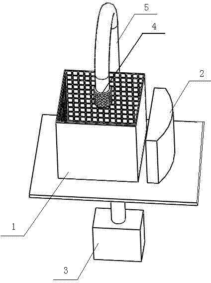
[0021] to combine figure 1 , figure 2 As shown, the particle accumulation force chain measurement device is composed of a pressure sensing container 1, a fluorescence spectrum detector 2, an air compressor 3, a hemispherical indenter 4 and its feeding device. In this embodiment, the feeding device is an inverted U The shaped bar 5 and the inverted U-shaped bar 5 are hollow, and the inverted U-shaped bar 5 is connected to the air compressor 3 below the platform, and the other end of the inverted U-shaped bar 5 is connected to the hemispherical pressure head 4, specifically, the inverted U-shaped bar 5 A retractable push rod is arranged at the end of the shaped rod 5, and the push rod is connected with the inverted U-shaped rod 5 through a chute, and a spring is also arranged between the pushed rod and the inverted U-shaped rod 5, and the push rod is fixed with the hemispherical pressure head 4 , the hemispherical pressure head 4 extends into the transparent pressure sensing c...

Embodiment 2

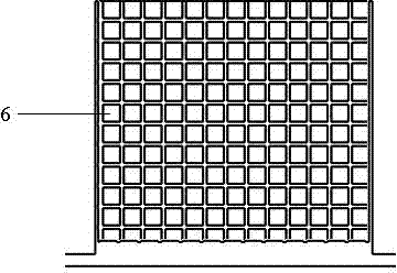
[0032] The difference between this embodiment and Embodiment 1 is that: the other three walls and the bottom surface of the pressure sensing container 1 are not provided with a piezoelectric induction sheet 6; . The measurement method of the particle force chain measuring device in this embodiment is:

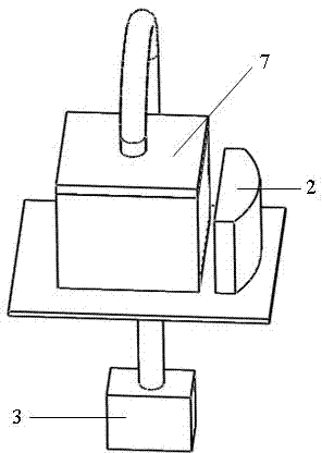
[0033] 1. Soak the particles in the pressure-sensitive paint, lift and release them several times, so that the surface of the particles is evenly coated with the pressure-sensitive paint, and after drying, put the particles into the pressure-sensitive container 1 and level them, and adjust the pressure head to the particle accumulation Above the object, cover the container lid 7, open the air compressor 3 and the fluorescence spectrum detector 2;

[0034] 2. Connect the excitation light source on the container cover, turn on the fluorescence spectrum detector 2, and adjust the air compressor 3 to push the pressure head to pressurize the particles, so that the particles and the...


PUM


Abstract

The invention relates to a device and a method for measuring force chains of particle deposits, wherein the device for measuring the force chains of the particle deposits comprises a pressure-sensing container, a fluorescence spectrum detector, an air compressor, a semispherical pressure head and a feeding device of the semispherical pressure head; the semispherical pressure head extends into thetransparent pressure-sensing container; the feeding device is connected with the air compressor; the fluorescence spectrum detector is arranged on one side face of the pressure-sensing container; onewall face of the pressure-sensing container corresponds to the fluorescence spectrum detector; a cover of the pressure-sensing container is provided with an excitation light source; and a power source connector is further arranged on the cover. With the adoption of the device and the method provided by the invention, the occurrence of the deposit of particulate matters can be effectively prevented, the transfer manner of the force chains of the particle deposits is clearly understood, and the guidance for how to effectively remove the debris deposited beds from boreholes can be provided.

Description

1. Technical field: [0001] The invention relates to a device for describing the internal force chain form of particle accumulations, and specifically relates to a measuring device and method for force chains of particle accumulations. 2. Background technology: [0002] A large amount of cuttings particles are produced during oil drilling, and the particles in the wellbore accumulate in the horizontal well section and the inclined well section to form a cuttings bed, which will cause drill sticking, poor pump, imperfect purification of cuttings at the bottom of the well, and repeated rock breaking by the drill bit , increase the useless work wear of the drill bit and the energy consumption of rock breaking, and at the same time, it may cause complex conditions in the downhole and affect the optimal and fast drilling. Existing studies on the network morphology of powder force chains mainly use indentation method and photoelastic experiment method. The photoelastic force chain...

Claims


Application Information

Patent Timeline
IPC IPC(8): G01L1/24
Inventor 李玮张杨闫铁王丽新王刚
Owner NORTHEAST GASOLINEEUM UNIV
Why Eureka
Try Eureka