Method and device for testing control cabinet of electric locomotive

A technology for electric locomotives and testing devices, applied in electrical testing/monitoring and other directions, can solve problems such as high cost, data loss, unfavorable maintenance, etc., and achieve the effect of improving real-time response rate, facilitating maintenance and upgrading, and meeting real-time requirements.

Active Publication Date: 2012-02-15
ZHUZHOU CSR TIMES ELECTRIC CO LTD
View PDF4 Cites 10 Cited by
  • Summary
  • Abstract
  • Description
  • Claims
  • Application Information

AI Technical Summary

Problems solved by technology

Generally speaking, the RAM area in the DSP chip is only 64K, and the storage space required by a motor model is about 30K, so it cannot meet the requirements for storing multiple motor models. In addition, the RAM area of ​​​​the DSP chip is a volatile storage space, that is, The data in the RAM area will be lost after power failure, which is not conducive to the application of on-site users
The size of the Flash storage area outside the DSP chip is generally 512K. Although it can meet the storage space requirements of multiple motor models to a certain extent, if all the motor models are written into the Flash area, it will be difficult for the maintenance and function of the later test equipment. Expansion brings inconvenience
For example, the user of a locomotive depot test bench only needs 5 types of locomotive electronic cabinet motor models, while another locomotive depot test bench user needs 8 types of locomotive electronic cabinet motor models. If different motor model libraries are programmed in the Flash area, is not conducive to unified maintenance
Even for users of the same test bench, if it involves function expansion, professionals must use professional tools to rewrite the Flash program, which leads to low work efficiency and high cost

Method used


Image

  • Method and device for testing control cabinet of electric locomotive
  • Method and device for testing control cabinet of electric locomotive
  • Method and device for testing control cabinet of electric locomotive

Examples


Embodiment Construction

[0079] The present application provides a test method and device for a control cabinet of an electric locomotive, which can not only meet the requirement of storing various motor models, but also facilitate the maintenance and function expansion of the test device.

[0080] In order to make the purpose, features, and advantages of the present application more obvious and understandable, the technical solutions in the embodiments of the present application will be clearly and completely described below in conjunction with the drawings in the embodiments of the present application.

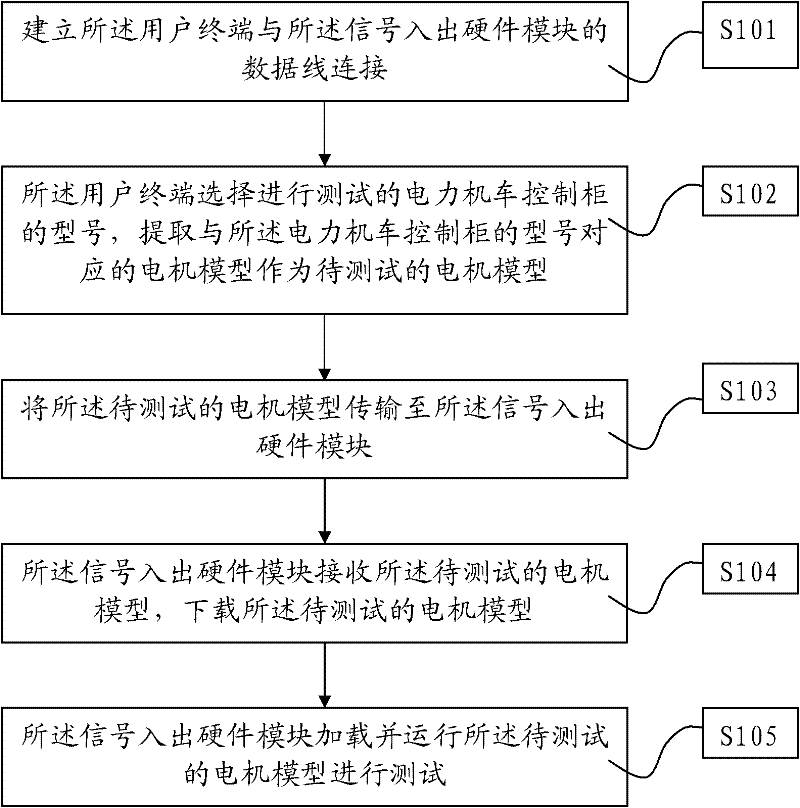
[0081] see figure 1 , is the flow chart of the first embodiment of the test method for the electric locomotive control cabinet of the present application.

[0082] The present application provides a test method for an electric locomotive control cabinet. The method uses an electric locomotive control cabinet test device to test the electric locomotive control cabinet. The electric locomotive control...


PUM


Abstract

The invention relates to the field of locomotive testing, in particular to a method and a device for testing a control cabinet of an electric locomotive. In the method, the device for testing the control cabinet of the electric locomotive is utilized to test the control cabinet of the electric locomotive; the device for testing the control cabinet of the electric locomotive comprises a user terminal and a signal input/output hardware module, and a motor model is stored in the user terminal. The method comprises the following steps: S1. establishing the user terminal connected with a data lineof the signal input/output hardware module; S2. selecting the type of the to-be-tested control cabinet of the electric locomotive by the user terminal, and extracting the motor model which corresponds to the type of the control cabinet of the electric locomotive to serve as the motor model to be tested; S3. transmitting the motor model to be tested to the signal input/output hardware module; S4. receiving the motor model to the tested by the signal input/output hardware module, and downloading the motor model to be tested; and S5. uploading and running the motor model to be tested to perform testing by the signal input/output hardware module.

Description

technical field [0001] The present application relates to the field of locomotive testing, in particular to a testing method and device for a control cabinet of an electric locomotive. Background technique [0002] The electric locomotive control cabinet is an important part of the electric locomotive control system. Its main function is to realize the traction and braking control of the locomotive by controlling the state of the motor. Its performance and operating status directly affect the functions of the electric locomotive control system. Therefore, an accurate test method is needed to test the electric locomotive control cabinet. [0003] In the prior art, the electric locomotive control cabinet testing device is usually used to simulate the motor model for testing. In the non-test state, store the motor model on the signal input and output hardware; during the test, run the motor model on the signal input and output hardware. The motor model is stored in the signal...

Claims


Application Information

Patent Timeline
Patent Type & Authority Applications(China)
IPC IPC(8): G05B23/02
Inventor 陈明奎戴仁德万加林苏理李鹏李小文罗继光黄亮
Owner ZHUZHOU CSR TIMES ELECTRIC CO LTD
Why Eureka
Try Eureka