
Device for high-precision measure of remote control response time

A technology of response time and measurement and control devices, applied in signal transmission systems, instruments, etc., can solve the problems of inaccurate response time and inaccurate time of remote control, and achieve the effect of ensuring work safety and high precision

Active Publication Date: 2012-02-15
FUJIAN YIRONG INFORMATION TECH
View PDF3 Cites 2 Cited by
  • Summary
  • Abstract
  • Description
  • Claims
  • Application Information

AI Technical Summary

Problems solved by technology

The remote control response time calculated in this way is inaccurate, because it not only includes the time for the corresponding action of the switching device (the time for the corresponding action of the switching device is not part of the remote control response time), but also because the switching device is fed back to the background. The time of the computer and the time when the remote control command is sent by the background machine will also be different due to the influence of the external environment, so if you simply divide it by two to deal with, the time obtained is not accurate

Method used

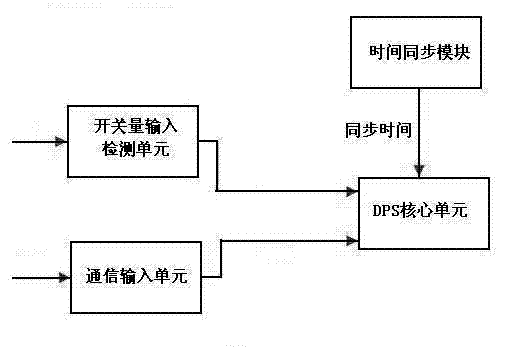

Image

  • Device for high-precision measure of remote control response time
  • Device for high-precision measure of remote control response time
  • Device for high-precision measure of remote control response time

Examples


Embodiment Construction

[0009] The present invention will be further described below in conjunction with accompanying drawing:

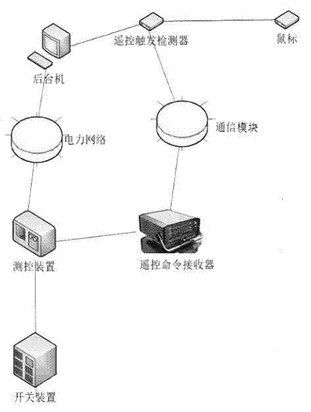
[0010] Such as figure 1 Shown is the connection diagram of the present invention. It can be seen from the diagram that the present invention includes a remote trigger detector connected to the mouse, a communication module and a background machine respectively, the communication module is connected to the measurement and control device through a remote command receiver, and the measurement and control device is connected to The background machine is connected, and the measurement and control device is also connected with the switch device.

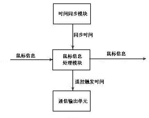
[0011] figure 2 It is a schematic diagram of the remote trigger detector of the present invention. It can be seen from the figure that the remote trigger detector of the present invention is composed of a time synchronization module connected with a communication output unit through a mouse information processing module.

[0012] Amo...


PUM


Abstract

A result of retrieval shows that the invention relates to an international patent classification (IPC) category G01S1 / 02 related to radio wave distance measurement or velocity measurement, and specially, relates to a device for high-precision measure of remote control response time. A technical scheme of the device for high-precision measure of remote control response time comprises that the device for high-precision measure of remote control response time comprises a remote control trigger detector; the remote control trigger detector is connected respectively with a mouse, a communication module and a backstage computer; the communication module is connected to a measurement and control device by a remote control command receiver; the measurement and control device is connected to the backstage computer by a power network; and the measurement and control device is connected to a switching device. The device for high-precision measure of remote control response time can measure directly remote control responses without other intermediate links, and thus compared with the prior art, the device for high-precision measure of remote control response time can realize higher precision in remote control response time measure.

Description

technical field [0001] After searching, the present invention relates to the category of G01S1 / 02 on the International Patent Classification (IPC) using radio waves for distance measurement or speed measurement, especially a device for measuring remote control response time with high precision. Background technique [0002] The test method of substation remote control response time in the prior art generally uses the staff to send remote control commands on the background machine, and record the sending time of the remote control commands; the switchgear of the substation receives the remote control commands and makes corresponding switching actions and then feeds back to the background machine. The computer receives the switching action information of the switch device, and records the feedback time; the background computer calculates the time difference between the two times, and divides the time difference by two to obtain the remote control response time. The remote cont...

Claims


Application Information

Patent Timeline
Patent Type & Authority Applications(China)
IPC IPC(8): G08C17/02
Inventor 倪时龙戴太文王小彬
Owner FUJIAN YIRONG INFORMATION TECH
Learn More