Supercharge Your Innovation With Domain-Expert AI Agents!

High-power microwave transmission antenna

A high-power microwave and transmission antenna technology, applied in directions such as antennas, antenna supports/installation devices, radiating element structures, etc., can solve the problems of narrow microwave frequency band width, large internal loss, inability to meet use requirements, etc., and achieve a simple structure. , the effect of low microwave loss

Active Publication Date: 2012-02-15
GUANGDONG WITOL VACUUM ELECTRONICS MFR
View PDF4 Cites 0 Cited by
  • Summary
  • Abstract
  • Description
  • Claims
  • Application Information

AI Technical Summary

Problems solved by technology

When it is applied to the microwave power of several hundred watts to more than 1000 watts, which is usually used in microwave ovens, it is easy to spark or even break down
At the same time, due to the presence of multiple tuning screws, this kind of microwave transmission antenna has a narrow microwave frequency bandwidth (generally fo±5MHz, where fo is the input microwave frequency) and large internal loss, which cannot meet the actual use requirements.

Method used


Image

  • High-power microwave transmission antenna
  • High-power microwave transmission antenna
  • High-power microwave transmission antenna

Examples


Embodiment 1

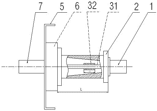
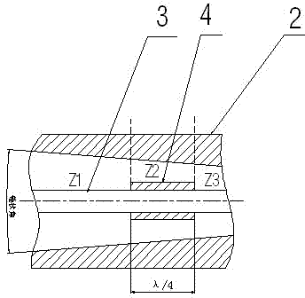
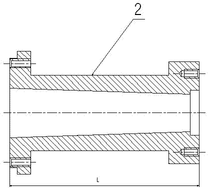
[0016] Such as figure 1 , figure 2 , image 3 As shown, the present invention includes a transmission antenna installation part and an impedance transformation part, wherein the transmission antenna installation part is composed of an installation base plate 5 and an installation base plate transition base 6, and the impedance conversion part is composed of an input high frequency connector 1, an antenna outer conductor 2, Antenna inner conductor 3 is formed, and the working wavelength of the input microwave signal of antenna is λ, and it is characterized in that, antenna outer conductor 2 inside is cavity structure, and the inner wall of cavity is the cone-shaped structure of the smooth transition that diameter continuously reduces, as image 3 As shown; the antenna inner conductor 3 is composed of a cylindrical thin rod 31 and a cylindrical antenna inner conductor matching block 32 installed coaxially along the thin rod 31 . The angle of the cone with smooth transition on...

Embodiment 2

[0019] Such as Figure 4 As shown, the difference between this embodiment and Embodiment 1 is that the inner wall of the cavity of the antenna outer conductor 2 is stepped, and the inner diameter of the step decreases step by step, and at the same time, the antenna inner conductor 3 is stepped and the antenna outer conductor 2 The inner wall of the cavity corresponds to a stepped cylinder whose diameter decreases step by step. In the present embodiment, the steps of the cavity inner wall of the antenna outer conductor 2 and the cylindrical body of the antenna inner conductor 3 have three steps, wherein the length of each step is λ / 4, and the phase between the antenna inner conductor 3 and the antenna outer conductor 2 The range of the distance a between the corresponding step surfaces is 0-2mm.

[0020] In this embodiment, as in Embodiment 1, according to the principle of impedance matching in the transmission line, the impedance of the transmission line at different sections...


PUM

PropertyMeasurementUnit
Angleaaaaaaaaaa
Diameteraaaaaaaaaa

Abstract

The invention relates to a high-power microwave transmission antenna, which comprises a transmission antenna installation part and an impedance conversion part. The transmission antenna installation part is composed of an installation base plate and an installation base plate transition substrate; and the impedance conversion part consists of an input high-frequency joint, an antenna outer conductor, and an antenna inner conductor. And an operating wavelength of an input microwave signal of the antenna is lambda. Besides, the transmission antenna is characterized in that: a cavity structure is arranged in the antenna outer conductor; and the antenna inner conductor is installed coaxially in the cavity; diameters of the cavity inner wall of the antenna outer conductor become smaller gradually with an extending direction from the installation direction and the input high-frequency joint along a direction of a central axis. According to the invention, the transmission antenna can be directly applied to high power microwave transmission and the working band of the transmission antenna is wide; moreover, an ignition phenomenon on the condition of high power transmission is eliminated; the microwave loss is lowest in the microwave transmission antenna; and an output power of a microwave power source can be effectively transmitted to a furnace chamber.

Description

technical field [0001] The invention relates to a microwave transmission antenna, in particular to a high-power microwave transmission antenna for household microwave ovens and industrial microwave equipment. Background technique [0002] Magnetron is a vacuum electron tube that generates microwaves. Because of its high oscillation efficiency and high microwave output power, it is widely used in household microwave ovens and microwave processing equipment such as industrial heating and chemical processing. In order to maximize the output power of the magnetron into the cavity of the microwave oven, a microwave transmission antenna equivalent to the output part of the magnetron is usually used, and the impedance of the cavity is adjusted at low power through a network analyzer to make it consistent with Magnetron impedance matching. This kind of microwave transmission antenna usually adopts a plurality of tuning screws distributed in the axial direction on the outer conduct...

Claims


Application Information

Patent Timeline
IPC IPC(8): H01Q1/12H01Q1/36H01Q13/08
Inventor 黄启先王彩育
Owner GUANGDONG WITOL VACUUM ELECTRONICS MFR
Features
  • R&D
  • Intellectual Property
  • Life Sciences
  • Materials
  • Tech Scout
  • Unparalleled Data Quality
  • Higher Quality Content
  • 60% Fewer Hallucinations
Learn More