

High-power microwave transmission antenna
A high-power microwave and transmission antenna technology, applied in directions such as antennas, antenna supports/installation devices, radiating element structures, etc., can solve the problems of narrow microwave frequency band width, large internal loss, inability to meet use requirements, etc., and achieve a simple structure. , the effect of low microwave loss
- Summary
- Abstract
- Description
- Claims
- Application Information
AI Technical Summary
Problems solved by technology
Method used
Image

Examples
Embodiment 1
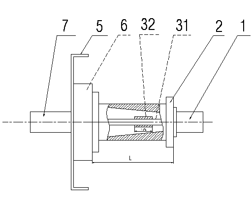
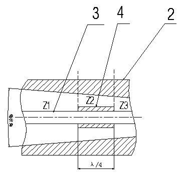
[0016] Such as figure 1 , figure 2 , image 3 As shown, the present invention includes a transmission antenna installation part and an impedance transformation part, wherein the transmission antenna installation part is composed of an installation base plate 5 and an installation base plate transition base 6, and the impedance conversion part is composed of an input high frequency connector 1, an antenna outer conductor 2, Antenna inner conductor 3 is formed, and the working wavelength of the input microwave signal of antenna is λ, and it is characterized in that, antenna outer conductor 2 inside is cavity structure, and the inner wall of cavity is the cone-shaped structure of the smooth transition that diameter continuously reduces, as image 3 As shown; the antenna inner conductor 3 is composed of a cylindrical thin rod 31 and a cylindrical antenna inner conductor matching block 32 installed coaxially along the thin rod 31 . The angle of the cone with smooth transition on...
Embodiment 2
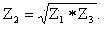
[0019] Such as Figure 4 As shown, the difference between this embodiment and Embodiment 1 is that the inner wall of the cavity of the antenna outer conductor 2 is stepped, and the inner diameter of the step decreases step by step, and at the same time, the antenna inner conductor 3 is stepped and the antenna outer conductor 2 The inner wall of the cavity corresponds to a stepped cylinder whose diameter decreases step by step. In the present embodiment, the steps of the cavity inner wall of the antenna outer conductor 2 and the cylindrical body of the antenna inner conductor 3 have three steps, wherein the length of each step is λ / 4, and the phase between the antenna inner conductor 3 and the antenna outer conductor 2 The range of the distance a between the corresponding step surfaces is 0-2mm.
[0020] In this embodiment, as in Embodiment 1, according to the principle of impedance matching in the transmission line, the impedance of the transmission line at different sections...
PUM
 Abstract
Description
Claims
Application Information