Exhaust turbine driven disk-type double-rotor permanent magnet generator

A permanent magnet generator and exhaust gas turbine technology, applied in electrical components, electromechanical devices, electric components, etc., can solve the problems of poor reliability, easy aging and failure of adhesives, easy damage, etc. Emission reduction effect

Inactive Publication Date: 2012-02-15
SHANDONG UNIV OF TECH
6 Cites 14 Cited by

AI-Extracted Technical Summary

Problems solved by technology

The technical solution is to bond multiple permanent magnets on the compressor impeller, or on the rotor main shaft, or on the back of the compressor impeller. Since the p...

Abstract

The invention provides an exhaust turbine driven disk-type double-rotor permanent magnet generator. The generator comprises a rotating shaft, a stator, a front end cover and a rear end cover. The generator is characterized in that the stator comprises stator supports sleeved on the rotating shaft at intervals and a plurality of iron cores embedded on the stator supports; armature windings are wound on the iron cores; the iron cores are uniformly distributed on the same circumference of the stator supports; a disk type rotor is additionally arranged at the two sides of the stator supports respectively and comprises a rotor disk fixedly sleeved on the rotating shaft and a plurality of rotor magnetic steel fixed on the rotor disk; the plurality of rotor magnetic steel fixed on the same rotor disk are fixed on the end faces, close to the stator supports, of the disk type rotors and are arranged on the same circumference; the polarities of the end faces, facing to the stator supports, of the adjacent rotor magnetic steel are opposite; and a certain axial clearances exist between the two disk type rotors and the stator. The generator has the following advantages that: the generator and the turbine share the same rotating shaft, has a compact structure, is convenient to install, takes up little space and is directly driven by the exhaust discharged by the engine, thus saving the energy.

Application Domain

Mechanical energy handling

Technology Topic

MagnetStator +2

Image

  • Exhaust turbine driven disk-type double-rotor permanent magnet generator
  • Exhaust turbine driven disk-type double-rotor permanent magnet generator
  • Exhaust turbine driven disk-type double-rotor permanent magnet generator

Examples

  • Experimental program(1)

Example Embodiment

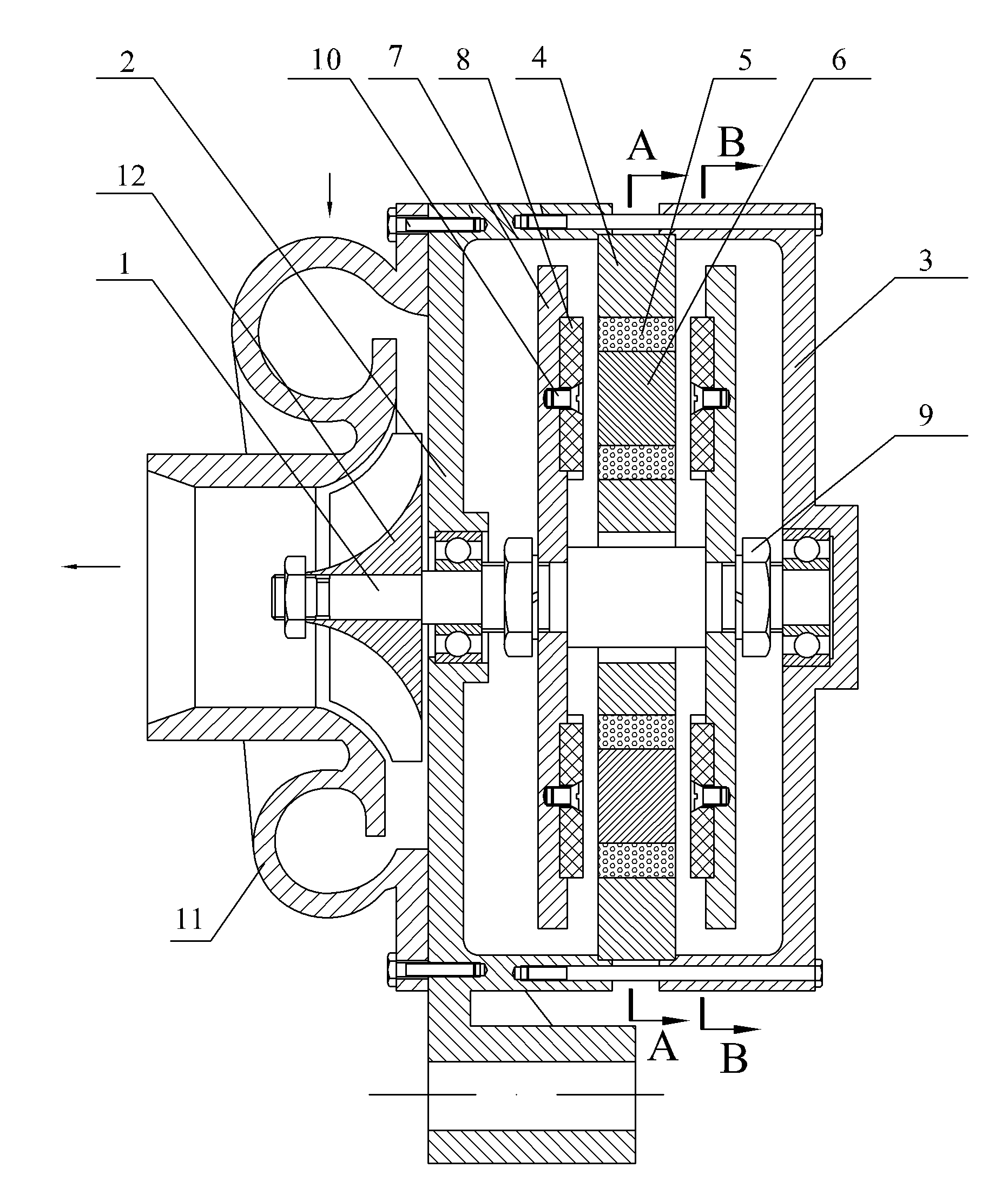
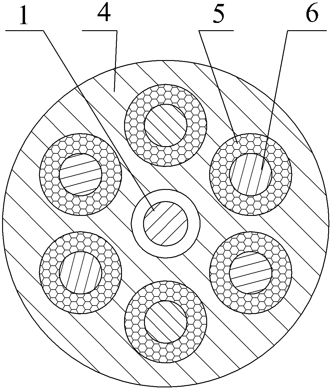
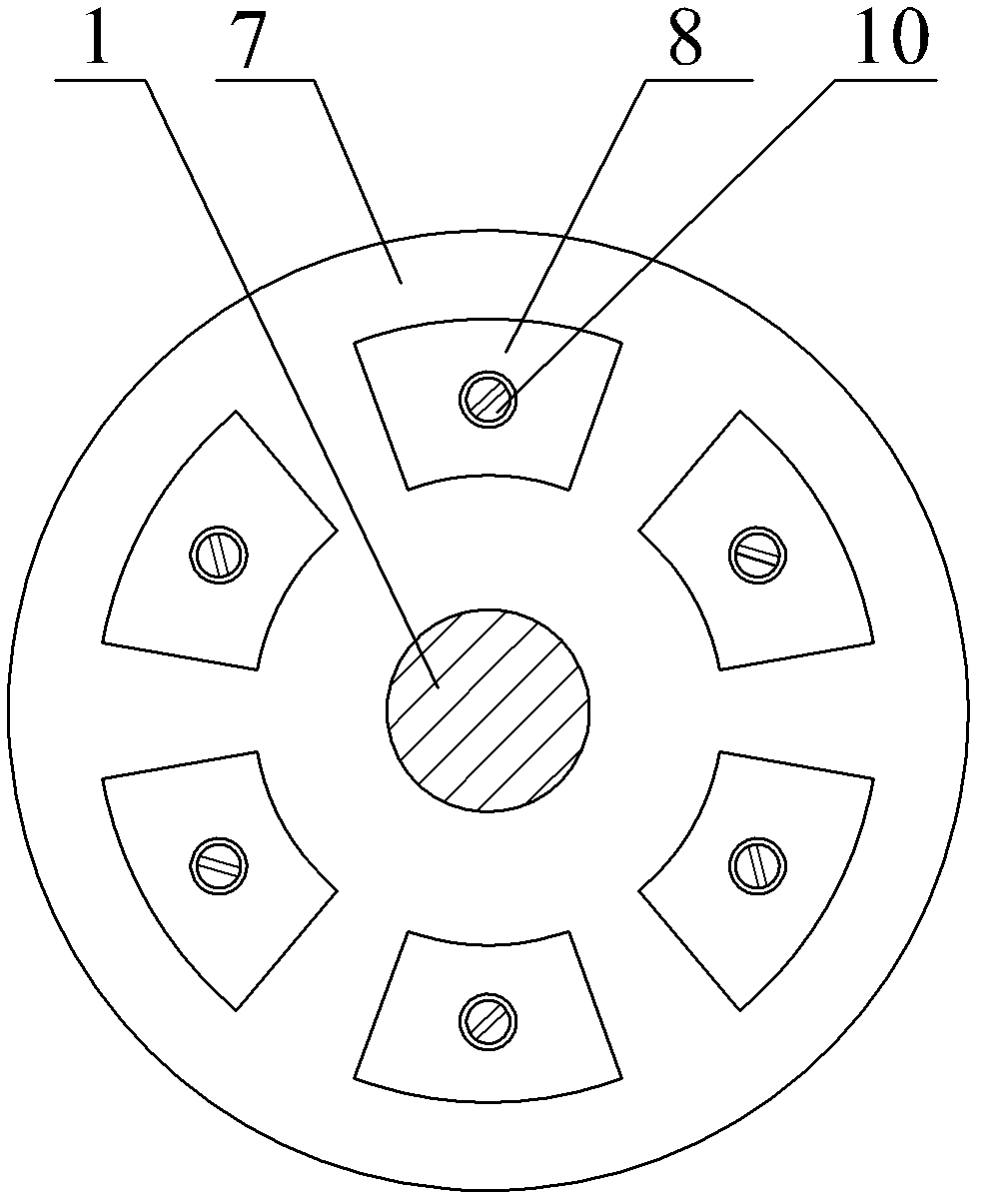
[0012] Attached below Figure 1-3 The present invention is further described:
[0013] The rotating shaft 1 of the generator and the rotating shaft of the turbine are the same shaft, the front end cover 2 and the rear end cover 3 are both mounted on the rotating shaft 1 with bearings, and the stator consists of a disc-shaped stator bracket 4 that is sleeved on the rotating shaft 1 with a gap and embedded in the rotating shaft 1. The stator bracket 4 is composed of a plurality of iron cores 6 wound with armature windings 5, wherein the iron cores 6 are evenly distributed on the same circumference of the stator bracket 4, and the number of turns of each armature winding 5 is equal, and the number of turns of the stator bracket 4 is equal. The outer edge is clamped and fixed by the front end cover 2 and the rear end cover 3, and the stator bracket 4 is coaxial with the front end cover 2 and the rear end cover 3; a disc rotor is added on both sides of the stator bracket 4, and each disc rotor is It includes a rotor disk 7 fixedly sleeved on the rotating shaft 1 and a plurality of rotor magnets 8 fixed on the rotor disk 7, wherein the plurality of rotor magnets 8 fixed on the same rotor disk 7 are all fixed on the disk type by screws 10. The rotor is close to the end face of the stator bracket 4 and is located on the same circumference, the polarity of the adjacent rotor magnets 8 facing the end face of the stator bracket 4 is opposite, and there is a certain axial gap between the two disc rotors and the stator.

PUM

no PUM

Description & Claims & Application Information

We can also present the details of the Description, Claims and Application information to help users get a comprehensive understanding of the technical details of the patent, such as background art, summary of invention, brief description of drawings, description of embodiments, and other original content. On the other hand, users can also determine the specific scope of protection of the technology through the list of claims; as well as understand the changes in the life cycle of the technology with the presentation of the patent timeline. Login to view more.

Similar technology patents

Novel flywheel energy storage device

ActiveCN104410204AShorten the axial lengthcompact structure
Owner:JIANGSU UNIV

Preparation method of CaCu3Ti4O12 ceramic

Owner:NORTHWESTERN POLYTECHNICAL UNIV

Automatic handing system of weight and application thereof

InactiveCN101806612AConvenient automatic handlingcompact structure
Owner:NAT INST OF METROLOGY CHINA

Roasted sausage and its production process

ActiveCN1810164ARuddy colorcompact structure
Owner:烟台喜旺肉类食品有限公司 +1

Classification and recommendation of technical efficacy words

  • compact structure
  • Easy to install

Cooking electric appliance

PendingCN107647763AEasy to installAvoid insulation loss
Owner:FOSHAN SHUNDE MIDEA ELECTRICAL HEATING APPLIANCES MFG CO LTD

System for monitoring vibration of rotating machinery rolling bearing in wireless mode

InactiveCN102053016Ameasurementanalysisdatareal-timeEasy to install
Owner:JIANGSU UNIV
Why Eureka
Try Eureka