Mechanical double energy storage impact mechanism and impact method

An impact mechanism and double energy storage technology, which is applied in the direction of power hammer and hammer driving device, etc., can solve the problem of high stress at the contact point between the impact head and the impacted object, high equipment cost and maintenance cost, and large working force of the pneumatic impact mechanism. problem, achieve good energy saving effect, reduce equipment and labor costs, and achieve accurate impact force

Inactive Publication Date: 2012-02-22
CHINA THREE GORGES UNIV
View PDF9 Cites 19 Cited by
  • Summary
  • Abstract
  • Description
  • Claims
  • Application Information

AI Technical Summary

Problems solved by technology

Among them, the pneumatic impact mechanism has a large working force, but the disadvantages of high equipment cost and maintenance cost, high cost of air source and other supporting devices, large footprint, and complicated layout limit its application; the traditional mechanical impact mechanism has a relatively simple structure. The equipment cost and maintenance cost are lower than those of pneumatic devices, so they are widely used; but because the mechanism is a rigid device, the contact time between the impact head and the impacted object is extremely short, so the negative acceleration of the impact head is large, and the stress at the contact point between the impact head and the impacted object Very large, it is easy to cause local deformation and damage

Method used


Image

  • Mechanical double energy storage impact mechanism and impact method
  • Mechanical double energy storage impact mechanism and impact method
  • Mechanical double energy storage impact mechanism and impact method

Examples


Embodiment

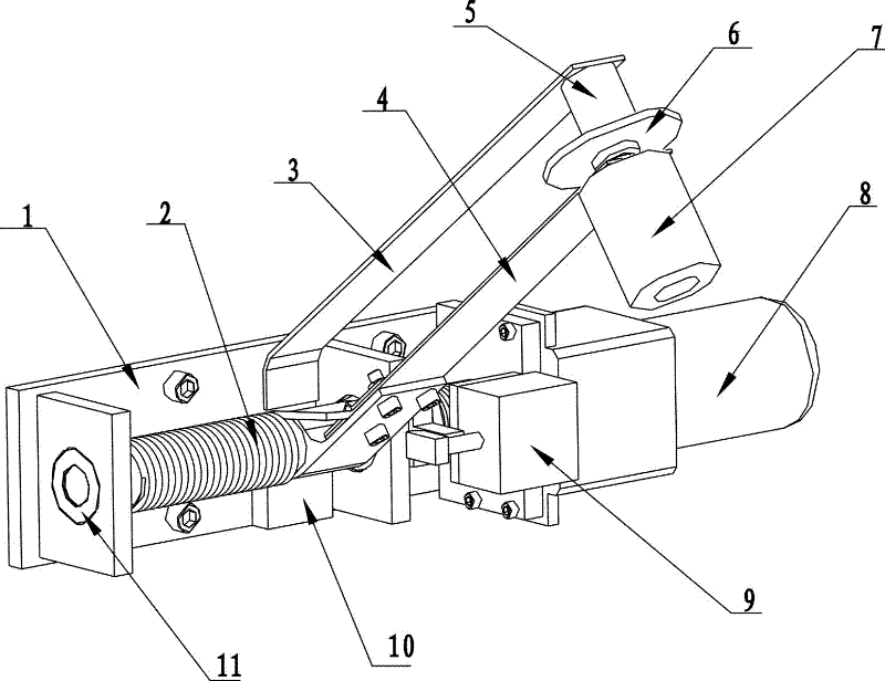
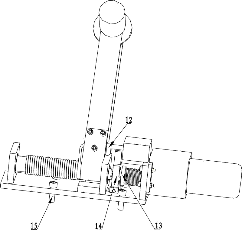
[0038] Such as figure 1 , figure 2 As shown, the mechanical double energy storage impact mechanism of the present invention consists of a frame 1, a torsion spring 2, an auxiliary positioning electromagnet mounting arm, a swing arm, an auxiliary positioning electromagnet, a suction plate 6, a hammer head 7, and an electric drive mechanism 8 , clutch electromagnet, buffer block 10, bearing 11, rotating shaft 12, drag hook 13, gear clutch 14, lever 15, mounting screw 16 and form.

[0039] The frame 1 plays a supporting role for the whole mechanism, and is installed on the corresponding position of the main equipment by screws 16 . The rotating shaft 12 is installed and positioned on the frame 1 through the bearing 11 . The torsion spring 2 and the rotating shaft 12 are coaxially installed, one end is fixed on the swing arm 4, and the other end is fixed on the frame 1.

[0040] The electric drive mechanism 8, the clutch electromagnet, and the buffer block 10 are installed on ...


PUM


Abstract

The invention discloses a mechanical double energy storage impact mechanism and a mechanical double energy storage impact method. The mechanism comprises a frame, a rotating shaft is arranged on the frame, the rotating shaft is fixedly connected with a swinging arm, the swinging arm is connected with a hammer head, a torsion spring is arranged coaxial with the rotating shaft, the swinging arm is fixedly connect to one end of the torsion spring, and the other end of the torsion spring is fixed on the frame. An electric driving mechanism and a first electromagnet are arranged on the frame, the first electromagnet is connected with a drag hook, a gear clutch is arranged on the electric driving mechanism, and a lever is movably connected to the frame and movably matched with the drag hook; and a second electromagnet is arranged on the frame through a mounting arm. The mechanism has two energy storage links, namely deformation energy storage of the torsion spring and elastic bending energystorage of the swinging arm, so that the contact stress during impacting can be effectively reduced and the working surface of a workpiece is well protected. By using the mechanism and the method, conventional heavy manual hammering can be replaced, and the labor intensity is lightened; and the mechanism can also be used for replacing the conventional starting pneumatic striker in the powder conveying process to prevent blockage.

Description

technical field [0001] The invention relates to a mechanical double energy storage impact mechanism and an impact method, belonging to the technical field of mechanical impact. Background technique [0002] Low-frequency hammering is widely used in the fields of powder conveying and mechanical processing. This operation requires the use of low-frequency and high-energy impact mechanisms. The currently used low-frequency high-energy impact mechanisms mainly include pneumatic impact mechanisms and mechanical impact mechanisms. Among them, the pneumatic impact mechanism has a large working force, but the disadvantages of high equipment cost and maintenance cost, high cost of air source and other supporting devices, large footprint, and complicated layout limit its application; the traditional mechanical impact mechanism has a relatively simple structure. The equipment cost and maintenance cost are lower than those of pneumatic devices, so they are widely used; but because the ...

Claims


Application Information

Patent Timeline
Patent Type & Authority Applications(China)
IPC IPC(8): B21J7/04B21J7/30B21J7/32
Inventor 邹隽张园李力张宗弋
Owner CHINA THREE GORGES UNIV
Why Eureka
Try Eureka