
Fixture

A fixture and positioning disc technology, which is applied in the field of parts processing, can solve the problems of low part processing pass rate, high scrap, cost increase, etc., and achieve the effect of fast mass production progress, high processing pass rate and accurate positioning

Inactive Publication Date: 2015-01-14
AVIC PST NANFANG GAS TURBINE COMPLETE MFG & INSTALLATION
View PDF5 Cites 0 Cited by
  • Summary
  • Abstract
  • Description
  • Claims
  • Application Information

AI Technical Summary

Problems solved by technology

[0005] The object of the present invention is to provide a fixture to solve the problem of inaccurate positioning of the machined surface of the machined parts, incomplete fixation of the parts, and movement of the parts during the machining process, resulting in a low processing pass rate of the parts, more scrapping, and increased costs. Technical problems that seriously affect the progress of mass production

Method used


Image

  • Fixture
  • Fixture
  • Fixture

Examples


Embodiment Construction

[0022] The embodiments of the present invention are described in detail below with reference to the accompanying drawings, but the present invention can be implemented in many different ways as defined and covered by the claims.

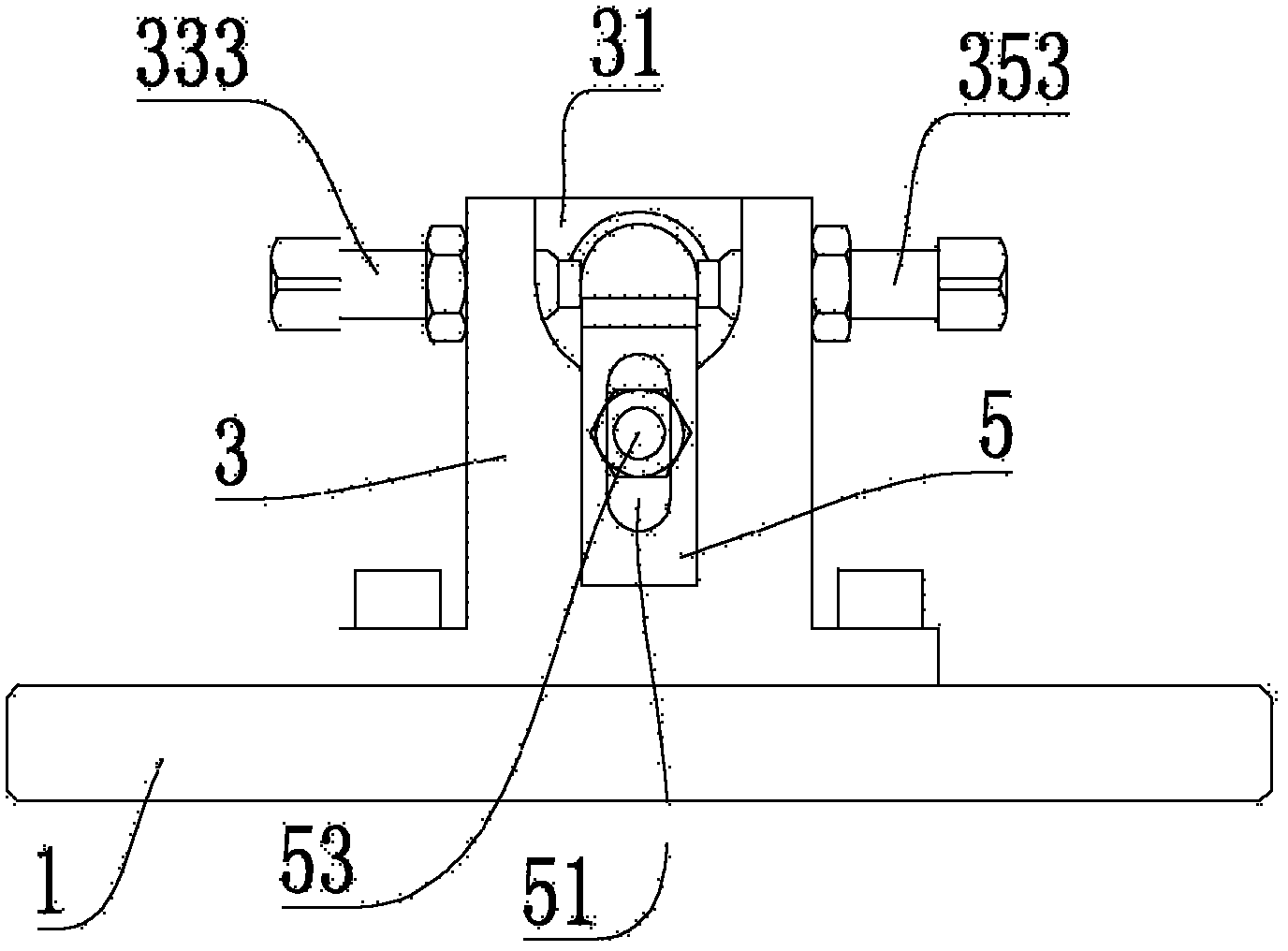
[0023] see figure 1 , the fixture includes a positioning plate 1 and a positioning block 3 fixedly mounted on the positioning plate 1 .

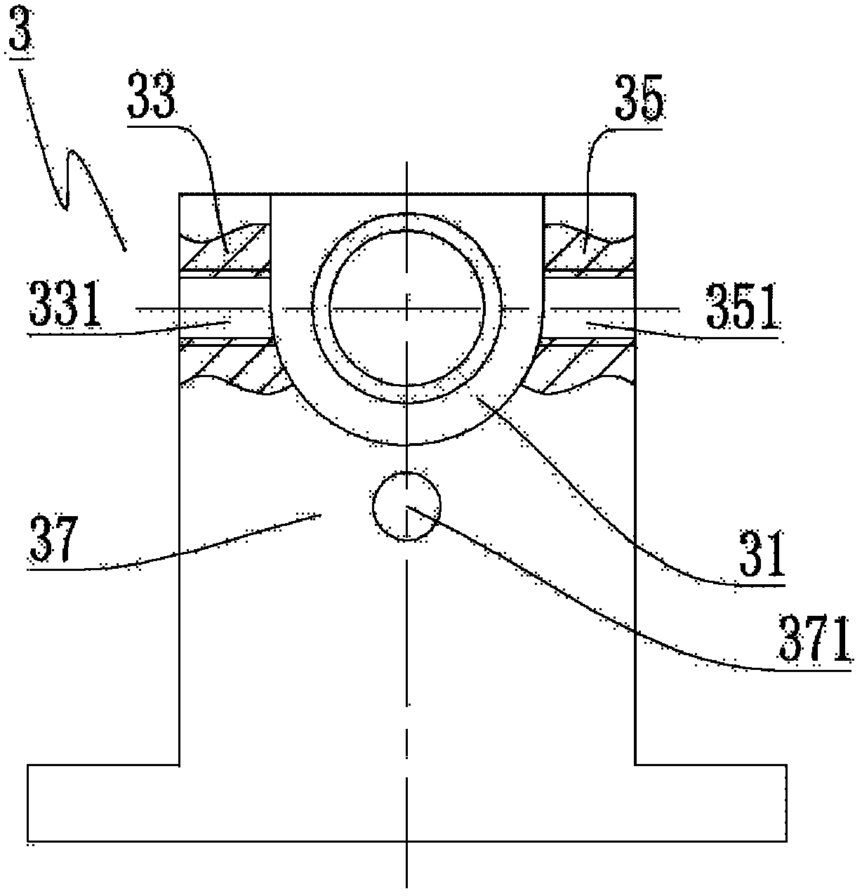
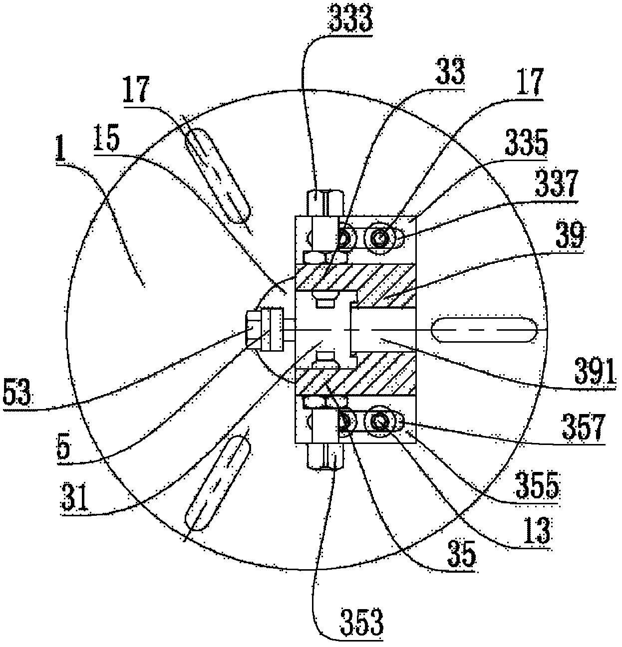
[0024] Please refer to figure 2 and image 3 , the positioning block 3 is provided with a positioning groove 31 . The positioning groove 31 is formed with a first wall 33 and a second wall 35 opposite to the first wall 33 . The first wall 33 and the second wall 35 are respectively provided with a first threaded hole 331 and a second threaded hole 351 penetrating the first wall 33 and the second wall 35 . The first threaded hole 331 and the second threaded hole 351 are respectively fitted with a first pressing screw 333 and a second pressing screw 353 . The first pressing screw 333 is also opposite to the seco...


PUM


Abstract

The invention provides a fixture, comprising a dowel disc and a positioning block, wherein the positioning block is adjustably fixedly installed on the dowel disc; the positioning block is provided with one positioning slot; the positioning slot comprises a first wall and a second wall which are opposite; the first wall and the second wall are respectively provided with a first operable compression screw and a second operable compression screw; a third wall is connected between the first wall and the second wall; the positioning slot extends to penetrate through the third wall; the third wall is provided with an operable platen; and the platen just faces to the positioning slot. According to the fixture, the machined surface of a part can be accurately positioned, and the part can be firmly fixed and does not move in the machining process so as to achieve the effect on high part machining percent of pass, small scrap, low cost and high volume production speed.

Description

technical field [0001] The invention relates to the field of parts processing, in particular, to a fixture for processing parts. Background technique [0002] In the prior art, if a round hole is to be turned on a part, the three claws that come with the machine tool are generally used to lightly clamp the three surfaces of the part, then locate the machined surface of the part, and then tighten the three claws to fix the part. , and finally turn the part and realize mass production of this part. [0003] However, this method has inaccurate positioning of the machined surface, incomplete fixation of parts, and parts will move during processing, resulting in many parts being unqualified after processing, more scrapped, and increased cost, which seriously affects the progress of mass production. [0004] Published in May 1981, "Mechanics. The "Radial Rotating 180° Car Valve Body Combination Fixture" recorded in the 4th issue of "Cold Working" discloses a combination fixture,...

Claims


Application Information

Patent Timeline
IPC IPC(8): B23Q3/00
Inventor 谭冬桂
Owner AVIC PST NANFANG GAS TURBINE COMPLETE MFG & INSTALLATION
Features
  • Generate Ideas
  • Intellectual Property
  • Life Sciences
  • Materials
  • Tech Scout
  • Unparalleled Data Quality
  • Higher Quality Content
  • 60% Fewer Hallucinations
Learn More