Supercharge Your Innovation With Domain-Expert AI Agents!

Safe elevator with brake in lift car

一种安全电梯、制动器的技术,应用在建筑物内的电梯、升降机、运输和包装等方向,能够解决拖长电梯交付使用的时间、影响住户正常生活、施工工期长等问题,达到缩短施工工期、缩短工期、提高安装质量的效果

Active Publication Date: 2013-10-16
张向阳
View PDF6 Cites 0 Cited by
  • Summary
  • Abstract
  • Description
  • Claims
  • Application Information

AI Technical Summary

Problems solved by technology

The long construction period of the bottom pit not only prolongs the delivery time of the elevator, but also brings great inconvenience to the residents of the building where they live, affecting the normal life of the residents to a certain extent

Method used


Image

  • Safe elevator with brake in lift car
  • Safe elevator with brake in lift car
  • Safe elevator with brake in lift car

Examples


Embodiment 1

[0033] Embodiment one: if Figure 6 As shown, the elevator described in the present embodiment comprises a hoistway wall 8, a car 2, and a counterweight 5. The car 2 runs in the hoistway wall 8, and the car 2 uses a wire rope 254 to pass through the traction sheave 112 and the guide pulley 121 and the counterweight 5. Heavy 5 connected.

[0034] This embodiment adopts the traction and drag mode of the existing elevator. The structure of each part of the elevator is the same as that of the existing traction elevator. The difference is that a main shaft 34 is installed on the car, and a car brake is added on the main shaft 34. 37. In order to ensure that the car brake 37 can work effectively, the sliding connection between the hoistway wall 8 and the car 2 is changed to a rack and gear meshing connection.

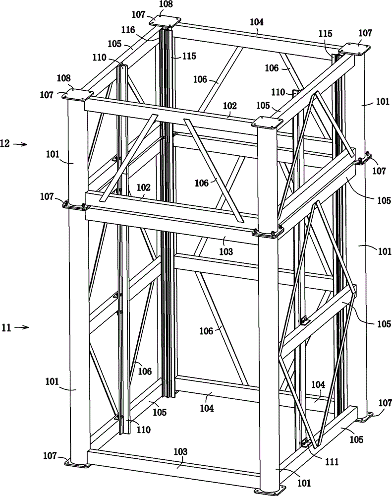
[0035] Such as Figure 12Shown, a kind of car is provided with the safety elevator of brake, comprises hoistway wall 8, car frame 21 and the car guide rail 110 that is loca...

Embodiment 2

[0040] Embodiment 2: This embodiment is basically the same as Embodiment 1, the difference is that the hoistway wall 8 is improved, and the hoistway wall 8 of this embodiment adopts a metal frame hybrid structure. Such as Figure 7 As shown, the hoistway wall 8 of this embodiment includes a well tower and a pit body 13. The well tower is assembled by laminating two or more steel structure derricks 1 through high-strength bolts according to the number of floors where the elevator is installed. Formed, the derrick at the bottom of the well tower is called the bottom derrick, and the bottom derrick is horizontally fixed on the bottom pit body 13 by high-strength bolts.

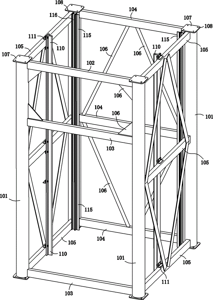
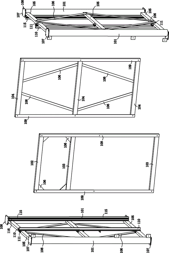
[0041] Such as figure 1 As shown, the derrick 1 includes 4 columns 101, 3 rear beams 104 and 3 left and right side beams 105 respectively. A connection seat 107 is provided, and four connection holes 108 are arranged on the connection seat 107 (in other embodiments, the number of connection holes 108 may also b...


PUM


Abstract

The invention discloses an elevator assembled by utilizing combination type derricks, relating to hoisting equipment. A hoistway wall of the elevator is formed by assembling more than two derricks, wherein each derrick comprises stand columns, a door beam, a front beam, a back beam, a left beam, a right beam, a cage guide rail and a counter-weight guide rail, wherein the four stand columns are distributed at four corners of the derrick, and connection seats are horizontally and fixedly arranged at the top end and the bottom end of each stand column and provided with connection holes; two ends of the door beam, the front beam, the back beam, the left beam and the right beam are transversely and respectively connected with the stand columns; and the cage guide rail and the counter-weight guide rail are respectively installed in the middle parts and the inner sides of the back ends of the left beam and the right beam. Because the derricks can be produced in a standardized way in a factory and assembled on site, the working time limit can be shortened, the cost can be lowered, the manufacturing cost can be reduced, and the installation efficiency and quality can be improved; and because the derricks are matched with an up-down door-opening and closing mechanism, the influence of the installed elevator on ventilation and daylighting of a household can be reduced. The elevator assembled by utilizing the combination type derricks is mainly used for places of low storey dwelling houses, in particular to the old style low storey dwelling houses of less than 9 storeys.

Description

technical field [0001] The invention-creation title of the prior application of the present invention is "an elevator assembled with a combined derrick", the application number is ZL201110000730.8, and the application date is January 4, 2011. [0002] The present invention relates to a hoisting device, in particular to an elevator. Background technique [0003] Although the traction technology of the existing elevator is very mature, the biggest defect of the traction drive is that the guide rail and the guide shoe are slidingly connected, the brake is installed on the traction machine, and the steel wire rope for the car passes through the traction sheave and the counterweight on the traction machine. The connection between the traction sheave and the wire rope is a friction transmission, and the reliability of the friction transmission is poor. Once the electronic control system fails or the wire rope and the traction sheave slip or even breaks, the brake will fail and cau...

Claims


Application Information

Patent Timeline
Patent Type & Authority Patents(China)
IPC IPC(8): B66B9/02B66B7/00
Inventor 张向阳
Owner 张向阳
Features
  • R&D
  • Intellectual Property
  • Life Sciences
  • Materials
  • Tech Scout
  • Unparalleled Data Quality
  • Higher Quality Content
  • 60% Fewer Hallucinations
Learn More