Low-distortion large-field image space telecentric optical device in

An optical device and large field of view technology, applied in optics, optical components, instruments, etc., to achieve high imaging quality, meet the uniformity of illumination in different fields of view, and simplify the system

Inactive Publication Date: 2012-02-22
ANHUI UNIVERSITY OF TECHNOLOGY
View PDF4 Cites 2 Cited by
  • Summary
  • Abstract
  • Description
  • Claims
  • Application Information

AI Technical Summary

Problems solved by technology

[0005] At present, there is no such telecentric optical device with large field of view and low distortion image space designed for monochromatic light in China.

Method used


Image

  • Low-distortion large-field image space telecentric optical device in
  • Low-distortion large-field image space telecentric optical device in
  • Low-distortion large-field image space telecentric optical device in

Examples


Embodiment Construction

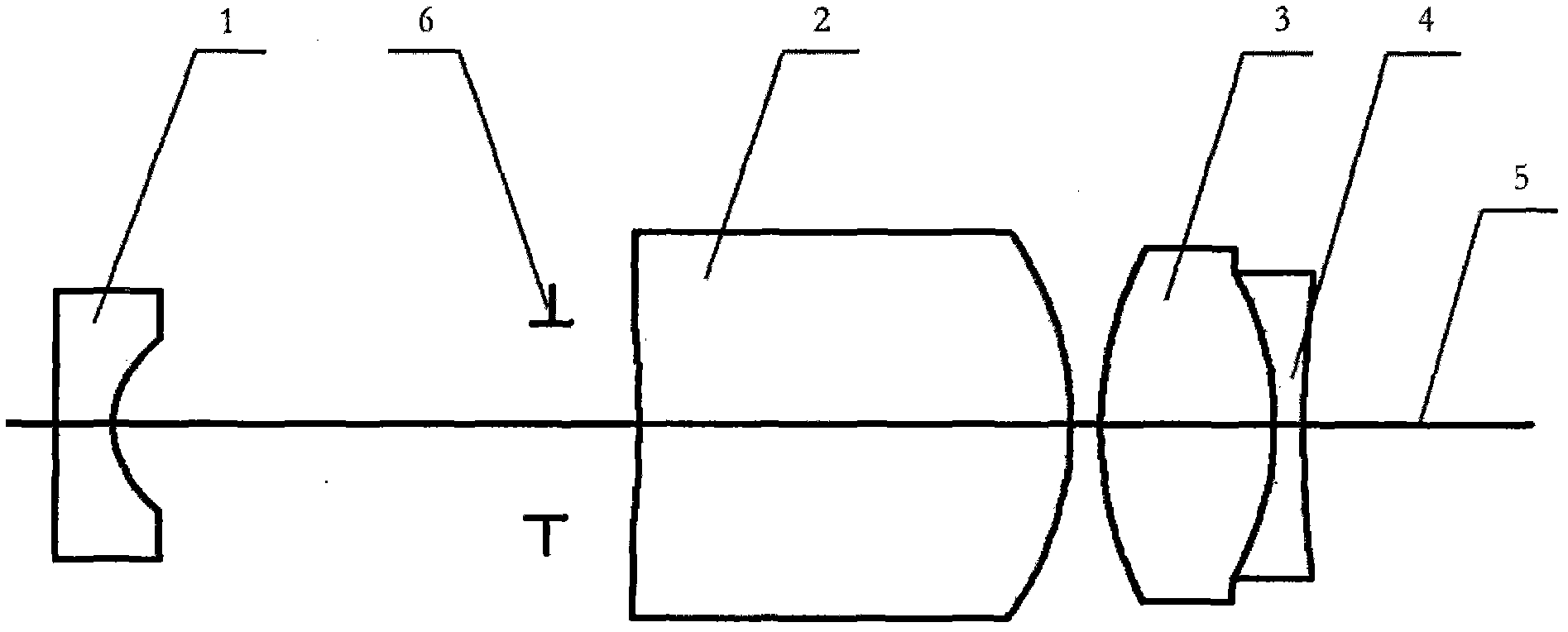
[0022] see figure 1 , the present invention provides a telecentric optical device with low distortion and large field of view using aspheric technology, the optical system includes a first negative lens 1, a diaphragm 6, a first positive lens 2, a second positive lens 3 and The second negative lens 4 ; the first negative lens 1 , the diaphragm 6 , the first positive lens 2 , the second positive lens 3 and the second negative lens 4 are sequentially arranged on the same optical path 5 .

[0023] In order to improve the imaging quality and reduce various aberrations, the second positive lens 3 and the second negative lens 4 are double-glued in the present invention, the first positive lens is a meniscus-shaped thick lens, and the first surface of the first negative lens 1 is a plane , the first surface of the first positive lens 2 is an even-order aspheric surface, and the other surfaces are standard spherical surfaces.

[0024] With the improvement of LED lighting technology, ...


PUM


Abstract

The invention relates to a low-distortion large-field image space telecentric optical device using an aspheric surface technology. The low-distortion large-field image space telecentric optical device comprises a first negative lens, a lens screen, a first positive lens, a second positive lens and a second negative lens which are sequentially arranged on the same light path, wherein the second positive lens and the second negative lens are glued, and the first surface of the first positive lens is an evenorder aspheric surface. The invention provides a front imaging device being designed aiming at 660 nano glow illumination and being capable of meeting high-precision measurement and full-filed illumination uniformity requirement and being applied to an optical fiber coherent fiber bundle.

Description

Technical field: [0001] The patent of the present invention belongs to the field of optical imaging, and relates to a telecentric optical device with low distortion and large field of view, in particular to an optical device suitable for measuring and observing endoscopic lenses such as optical fiber image beam lenses. Background technique: [0002] The optical fiber image transmission bundle is a fiber optic component that regularly gathers a plurality of optical fibers of a certain length into a bundle to transmit images. It is also a passive device that can be bent arbitrarily to transmit images. Due to its unique irreplaceable characteristics, it is widely used in many fields such as medicine, industry, scientific research, military and so on. General applications do not require high imaging quality, and the front imaging objective lens is relatively simple. With the development of CCD imaging technology and large cross-section optical fiber image beam technology, in so...

Claims


Application Information

Patent Timeline
Patent Type & Authority Applications(China)
IPC IPC(8): G02B13/22G02B13/06G02B13/18G02B1/00
Inventor 王伟范经纬张清孙文斌
Owner ANHUI UNIVERSITY OF TECHNOLOGY
Why Eureka
Try Eureka