Infrared thermal imaging optical system and application thereof

An infrared thermal imaging and optical system technology, which is applied in the optical field to achieve high spatial resolution imaging capability, low distortion in the full field of view, and high imaging resolution.

Active Publication Date: 2021-06-01
FOSHAN UNIVERSITY
View PDF5 Cites 2 Cited by
  • Summary
  • Abstract
  • Description
  • Claims
  • Application Information

AI Technical Summary

Problems solved by technology

At present, the infrared optical system in thermal imaging equipment is difficult to meet the above requirements

Method used


Image

  • Infrared thermal imaging optical system and application thereof
  • Infrared thermal imaging optical system and application thereof
  • Infrared thermal imaging optical system and application thereof

Examples


Embodiment

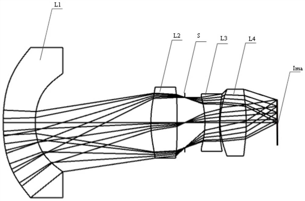
[0043] Such as Figure 1 to Figure 6 As shown, the infrared thermal imaging optical system of the present invention sequentially includes a meniscus negative refractive power lens L1, a biconvex positive refractive power lens L2, a diaphragm S, and a double concave negative refractive power lens along the optical axis from the object plane to the image plane Ima. Lens L3 and biconvex positive power lens L4. Wherein, an aperture stop S is provided between the double-convex positive lens L2 and the double-concave negative lens L3. In addition, the surface types of the meniscus negative lens L1 , the biconvex positive lens L2 , the biconcave negative lens L3 and the biconvex positive lens L4 are all spherical or aspherical. In order to reduce the distortion and high-level aberration caused by the large-angle incident light entering the optical system, the reciprocal 1 / γ of the angular magnification of the off-axis chief ray of the meniscus-shaped negative focal power lens L1 sat...


PUM


Abstract

The invention provides an infrared thermal imaging optical system. The system sequentially comprises a meniscus negative power lens L1, a biconvex positive power lens L2, a diaphragm S, a biconcave negative power lens L3 and a biconvex positive power lens L4 from an object plane to an image plane along an optical axis. The reciprocal 1/gamma of the angular magnification of the meniscus negative-power lens L1 to the off-axis chief light meets the condition that 1/gamma is larger than or equal to 1.5 and smaller than or equal to 2.4. The invention further provides application of the infrared thermal imaging optical system in the medical field. The infrared thermal imaging optical system realizes optical system design with large relative aperture, large field of view and high illumination uniformity, has high spatial resolution imaging capability, realizes the capabilities of low noise equivalent temperature difference and large imaging field of view, can meet the temperature measurement requirement of infrared thermal imaging equipment for a high-performance infrared optical system, and facilitates wide application and popularization in the medical technology.

Description

technical field [0001] The invention relates to the field of optical technology, more specifically, to an infrared thermal imaging optical system and its application. Background technique [0002] In the medical field, infrared thermal imaging technology is used to collect thermal radiation signals on the surface of the human body and accurately measure the temperature field distribution in various regions of the human body for human health examination and pathological diagnosis. It is becoming a new dimension of auxiliary diagnostic methods. In the field of western medicine, infrared thermal imaging technology is applied to human health examination and research on the physiological and pathological responses of diseases. For example, a clinical research report in the United States pointed out that infrared thermal imaging diagnostic technology can detect tumors 6 to 12 months earlier than CT. There is a close correlation between infrared thermography diagnostic method and ...

Claims


Application Information

Patent Timeline
Patent Type & Authority Applications(China)
IPC IPC(8): G02B13/00G02B13/06G02B13/14G02B13/18A61B5/01
CPCG02B13/004G02B13/005G02B13/008G02B13/06G02B13/14G02B13/18A61B5/01
Inventor 伍雁雄项阳王丽萍谭海曙
Owner FOSHAN UNIVERSITY
Why Eureka
Try Eureka