
Flat wire vertical winding machine

A vertical winding and flat wire technology, applied in the field of flat wire vertical winding machines, can solve the problems of a lot of wire consumption, complicated winding process, unstable current output of the welding machine, etc.

Active Publication Date: 2012-02-22
YUNNAN JUFENG ELECTRIC WELDING MACHINE
View PDF2 Cites 7 Cited by
  • Summary
  • Abstract
  • Description
  • Claims
  • Application Information

AI Technical Summary

Problems solved by technology

However, after using the stays for the interlayer pads, there are always non-standard and non-uniform coil widths and dimensions, resulting in more wire consumption and relatively complicated winding processes. At the same time, the productivity is reduced and the product cost is increased.
There is also the problem that the current output of the welding machine is unstable. The technical indicators of the batch products of the welding machine are difficult to standardize and cannot be accurate and consistent, which affects the reduction of the use effect of the welding machine

Method used


Image

  • Flat wire vertical winding machine
  • Flat wire vertical winding machine
  • Flat wire vertical winding machine

Examples


Embodiment Construction

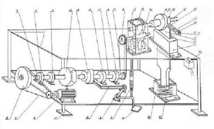
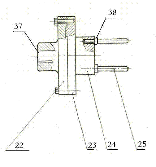
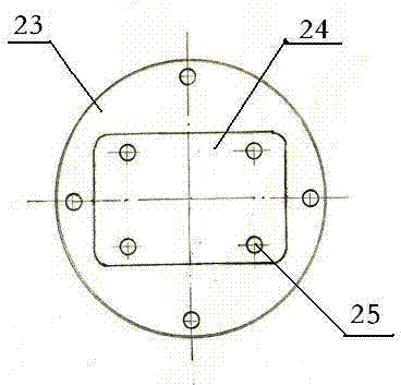
[0024] Below in conjunction with accompanying drawing, scheme is further described as an embodiment. refer to figure 1 , 2 , 3, 4, 5, 6, 7, 8:

[0025] The frame 5 of the flat wire vertical winding machine is made of upper and lower decks and four corners of the legs. Motor 6, belt 7, pulley 8, power transmission shaft 9, bearing housings 10, 11, and cone-disc clutch 12 are all installed on the front half of the lower platen, wherein the pulley at the motor shaft end and the pulley at the outer end of the cone-disk clutch 12 shaft form a deceleration fit form , to meet the welding machine coil winding speed requirements; two bearings 10 and 11 are fixed on the lower plate. The cone clutch 13 is fixed on the lower platform through the clutch bearing housings 14, 16, and the axis is on the same line as the aforementioned cone clutch; The big sprocket wheel of worm screw 21 outer ends cooperates unanimously, and two sprocket wheels form sprocket wheel group 18, and cover han...


PUM


Abstract

The invention relates to a flat wire vertical winding machine which mainly comprises a vertical winding wire shift device, a vertical winding die head device, a vertical winding compression device, a power drive device and a control device, wherein a wire shift strengthening block in the vertical winding wire shift device is fixed onto a connecting platform at the rear end of a guide head by a screw; a wire shift device is fixed on the wire shift strengthening block by a screw, and one upper-strip-shaped side of the wire shift device is provided with a wire shift groove; the front end of the guide head is provided with parallel guide wheel grooves and a vertical guide wheel groove; and two parallel guide wheels and a vertical guide wheel are respectively installed in the parallel guide wheel grooves and the vertical guide wheel groove correspondingly and connected with compression device sliding blocks by bolts. The vertical winding compression device comprises a sliding block support seat, an embedded strip, the sliding blocks, a compression spring and a spring support seat; and the vertical winding die head device comprises a ring flange, a flange connecting block, a die head and a coil lifting rod. A flat wire of a secondary coil of a welding machine is vertically wound, a coil width surface has more contact space, and thereby the heat is easy to radiate during loading; and the flat wire vertical winding machine not only can be used to ensure the contour dimension and the width surface size of the coil but also has the advantages of saving materials and ensuring stable current output at the same time.

Description

technical field [0001] The invention relates to a flat wire vertical winding machine. Background technique [0002] In the professional production technology of electric welding machine products, the winding material of the secondary coil of the welding machine is flat wire, which has been flat-wound for a long time, and the heat dissipation area between the wires of the wound coil is small. The rise is within the standard range. When winding the coil, it is generally used to place a stay between the coil layers to make it have a ventilation channel to increase the heat dissipation and cooling effect. However, after using the stays for the interlayer pads, there are always non-standard and non-uniform coil widths and external dimensions, resulting in more wire consumption and relatively complicated winding processes. At the same time, the productivity is reduced and the product cost is increased. There is also the problem that the current output of the welding machine is un...

Claims


Application Information

Patent Timeline
IPC IPC(8): H01F41/06H01F41/061H01F41/077H01F41/082H01F41/098
Inventor 张德明李国荣陈晗陈文毕
Owner YUNNAN JUFENG ELECTRIC WELDING MACHINE
Learn More