Pressure relief port assembly of gas insulated cabinet

A technology of gas insulation and pressure relief, which is applied in the direction of electrical components, switchgear, and switchgear settings. It can solve problems such as installation difficulties, restrict the design position of pressure relief parts, and increase labor intensity, so as to improve quality and sealing performance. Easy to arrange and combine, reduce labor intensity

Inactive Publication Date: 2012-02-22
JIANGSU DECOM ELECTRICS
View PDF6 Cites 11 Cited by
  • Summary
  • Abstract
  • Description
  • Claims
  • Application Information

AI Technical Summary

Problems solved by technology

[0004] This pressure relief part is installed at the assembly production site, and the static sealing pressure and pressure relief pressure are guaranteed by the bolt tightening pressure, so there are often human reasons that the bolts are not tightened to the design torque or due to environmental factors during the installation process. Dust or foreign matter is trapped on the sealing surface, and finally the airtightness of the air box cannot meet the design requirements, and the standardization and mass production of the pressure relief part cannot be realized, and its production quality and sealing performance cannot be guaranteed.
In addition, since the pressure relief part is directly installed on the outer surface of the air box, it is necessary to consider whether the installation is convenient or whether it can be sealed during design, which greatly restricts the design position of the pressure relief part
When installed at the assembly production site, the air box is relatively large in size, heavy in weight or inconvenient for installation, resulting in difficulty in installation and increased labor intensity

Method used


Image

  • Pressure relief port assembly of gas insulated cabinet
  • Pressure relief port assembly of gas insulated cabinet
  • Pressure relief port assembly of gas insulated cabinet

Examples


Embodiment Construction

[0019] Below in conjunction with accompanying drawing and embodiment, the present invention is further described:

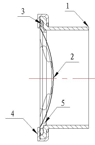
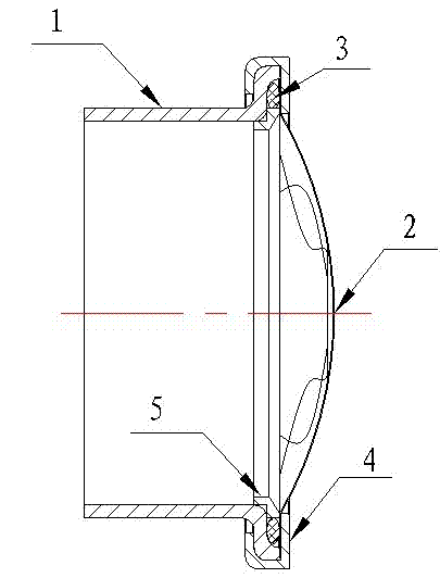
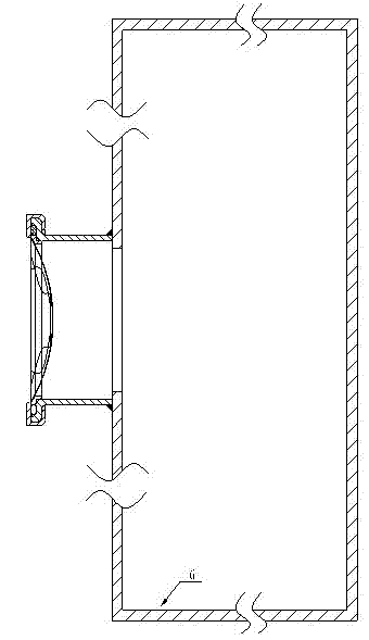
[0020] figure 1 Shown is a schematic diagram of the structure of the external pressure relief port in the present invention. The port is composed of a protective support welding cylinder 1, a pressure relief membrane 2, a sealing O-ring 3, a sealing pressing member 4, and a guide bushing ring 5. The protective support welding cylinder 1 is made of stainless steel or the same base material as that of the air box by stretching through a mold, and is used for sealing and welding on the outer surface of the air box 6. One end is the welding end, and the other end is the sealing installation end. The number of supporting welding cylinders depends on the size of the gas box, one for small-capacity gas boxes; three or two for large-capacity or large-capacity gas boxes. The box is sealed and welded into one. The pressure relief film 2 is made of a thin stainless steel...


PUM


Abstract

The invention discloses a pressure relief port assembly of a gas insulated cabinet. The assembly comprises a protection support welding cylinder, a pressure relief membrane, a sealed O-shaped ring and a sealed compaction member. The protection support welding cylinder is sealedly welded at an outer surface of a gas tank; one end of the protection support welding cylinder is a welding end and the other end is a sealed installation end; and the two ends respectively have openings. an outer edge of the pressure relief membrane is covered by the sealed O-shaped ring and is fastened at the sealed installation end of the protection support welding cylinder by the sealed compaction member. According to the invention, the assembly is suitable for standardized and batch production of port assemblies; qualities and sealing performances of the port assemblies are improved; and it is convenient for flexible arrangements and combination of the port assemblies as well as adjustments of heights and spacings of the port assemblies; besides, the labor intensity of assembly and production workers at the production site is improved and the production efficiency is enhanced.

Description

[0001] technical field [0002] The invention relates to a pressure relief port assembly of a gas insulated cabinet, by means of which the traditional pressure relief port of the gas insulated cabinet can be standardized and batched, the flexible arrangement and combination of the ports can be facilitated, the quality and sealing performance of the ports can be improved, and labor can be reduced Strength increases productivity. Background technique [0003] The pressure relief part of the existing gas insulated cabinet is directly installed on the outer surface of the gas box. After the welding of the air box is completed or the components inside the air box are installed, the parts that make up the pressure relief assembly are installed on the outer surface of the air box through bolts, and the "O" ring is used to form a static seal to ensure the air The airtightness of the box. [0004] This pressure relief part is installed at the assembly production site, and the stati...

Claims


Application Information

Patent Timeline
Patent Type & Authority Applications(China)
IPC IPC(8): H02B13/025
Inventor 王俊孟斌蒋川良潘飞雄
Owner JIANGSU DECOM ELECTRICS
Why Eureka
Try Eureka