
Bus reactive power optimization compensation controller

A compensation controller and controller technology, applied in reactive power compensation, reactive power adjustment/elimination/compensation, etc., can solve problems such as high cost, low degree of automation, and poor economic benefits, and achieve low cost and high degree of automation , design reasonable effect

Inactive Publication Date: 2012-02-22
山东康润电气股份有限公司
View PDF5 Cites 3 Cited by
  • Summary
  • Abstract
  • Description
  • Claims
  • Application Information

AI Technical Summary

Problems solved by technology

When the capacitor cannot be removed manually, it is necessary to equip an MCR with the same capacity as the fixed capacitor bank to realize the smooth stepless adjustment of the reactive power of the system, but the cost of the whole set of equipment is too high, the economic benefit is poor, and the degree of automation is low

Method used


Image

  • Bus reactive power optimization compensation controller
  • Bus reactive power optimization compensation controller
  • Bus reactive power optimization compensation controller

Examples


Embodiment Construction

[0015] Embodiments of the present invention are further described below in conjunction with accompanying drawings:

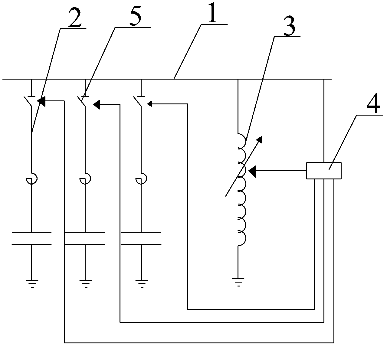
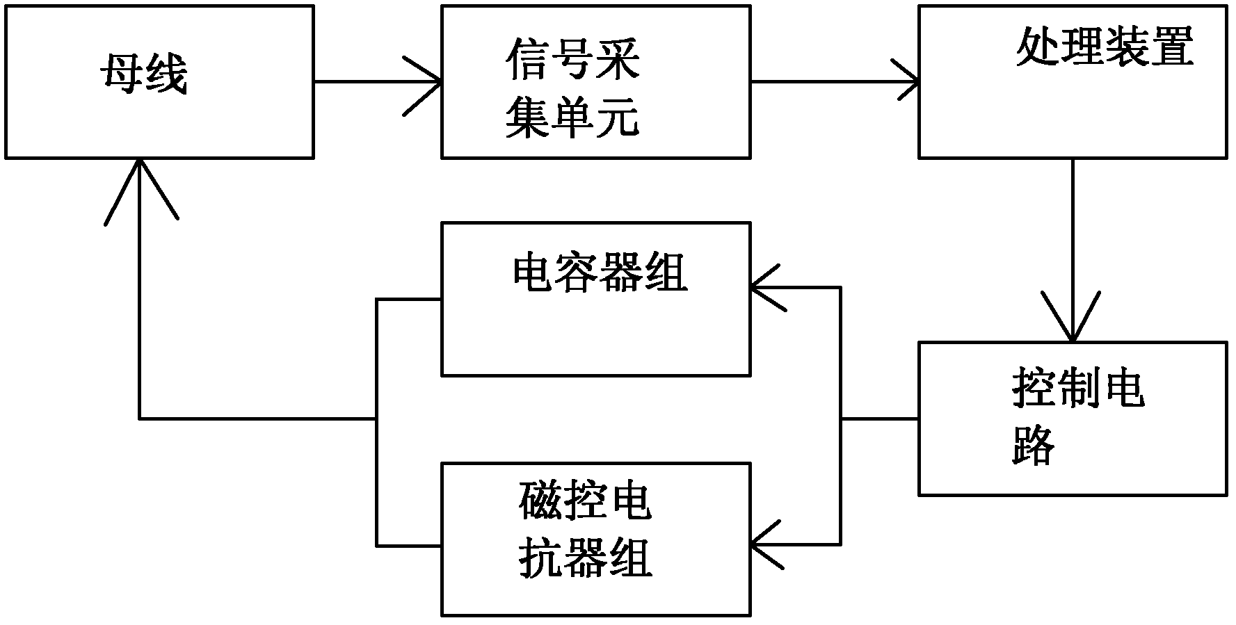
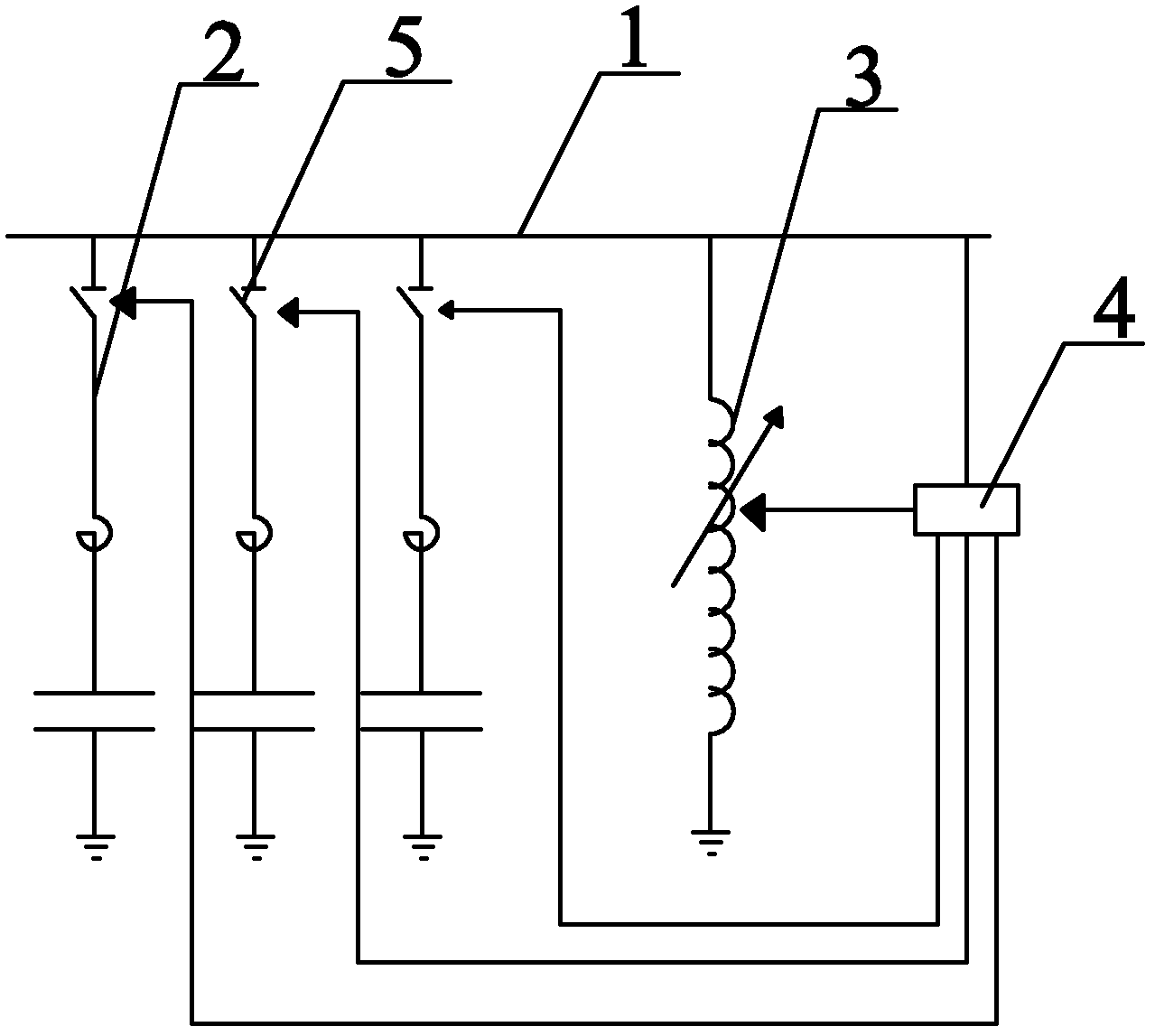
[0016] like Figure 1 ~ Figure 2 As shown, a busbar reactive power optimization compensation controller includes a busbar 1, a capacitor bank 2 and a magnetically controlled reactor bank 3, the capacitor bank 2 is connected in parallel with the busbar 1, and the magnetically controlled reactor bank 3 is set correspondingly to the capacitor bank 2 , connected to the bus bar 1, the capacitor bank 2 is connected to the bus bar 1 through the switching switch 5, the magnetron reactor bank 3 is connected to the bus bar 1 through the controller 4, and the controller 4 is also connected to the capacitor bank 2. The controller 4 includes a signal acquisition unit, a processing device and a control circuit. The bus 1 is connected to the processing device through the signal acquisition unit. The processing device is connected to the control circuit. The control circuit is ...


PUM


Abstract

The invention relates to a bus reactive power optimization compensation controller and belongs to the field of power equipment. The bus reactive power optimization compensation controller comprises a bus, a capacitor group and a magnetically controlled reactor group, wherein the capacitor group is arranged in parallel and connected with the bus; and the magnetically controlled reactor group is arranged corresponding to the capacitor group and connected with the bus. The bus reactive power optimization compensation controller is characterized in that: the capacitor group is connected with the bus through a fling-cut switch; and the magnetically controlled reactor group is connected with each capacitor of the capacitor group respectively through a controller. The bus reactive power optimization compensation controller has a simple and effective structure. A processing device has high calculation capacity. After a numerical value requiring reactive power compensation is calculated, the capacitor group required to be used is selected to perform capacitive reactive power compensation and inductive reactive power compensation through the magnetically controlled reactor group according to the actual condition, and the reactive power compensation for the bus can be realized without the magnetically controlled reactor group with the same capacitance as that of the fixed capacitor group. The bus reactive power optimization compensation controller has the advantages of low cost and high automation degree.

Description

technical field [0001] The invention relates to a busbar reactive power optimization compensation controller, which belongs to the field of electric equipment. Background technique [0002] Traditional reactive power compensation controllers use fixed-capacity capacitor banks and magnetically controlled reactor banks. By sampling the reactive power of the power bus system, the switching of capacitor banks and magnetically controlled reactor banks is controlled to achieve reactive power level regulation. Improve the power factor; since the capacity of the capacitor and the reactor are fixed values, it cannot realize the wireless continuous adjustment of reactive power, and the adjustment method is discrete, so that most of the time the power supply bus is under-compensated or over-compensated, and cannot be obtained. Ideal compensation effect, and the closing inrush current and switching shock caused by frequent switching of the container will cause serious damage to the serv...

Claims


Application Information

Patent Timeline
Patent Type & Authority Applications(China)
IPC IPC(8): H02J3/18
CPCY02E40/30
Inventor 陈津栾庆宏文刚刘海龙
Owner 山东康润电气股份有限公司
Learn More