Dry flue gas desulfurization process method and dry flue gas desulfurization system thereof

A dry desulfurization and process method technology, applied in separation methods, chemical instruments and methods, dispersed particle separation, etc., can solve problems such as lowering, secondary pollution of boiler output power, unusable mixing of slag and desulfurization products, etc. Simple control, low processing cost and small equipment investment

Inactive Publication Date: 2012-02-29
莫沙纱 +2
View PDF8 Cites 24 Cited by
  • Summary
  • Abstract
  • Description
  • Claims
  • Application Information

AI Technical Summary

Problems solved by technology

[0003] The problem to be solved by the present invention is to provide a flue gas dry desulfurization process. Compared with the existing dry desulfurization technology, it can solve the problem that the mixture of sl...

Method used


Image

  • Dry flue gas desulfurization process method and dry flue gas desulfurization system thereof
  • Dry flue gas desulfurization process method and dry flue gas desulfurization system thereof

Examples


Embodiment 1

[0039] Embodiment 1——The flue gas dry desulfurization process method of a thermal power plant that burns 3000 tons of bituminous coal with a sulfur content of 4% per day:

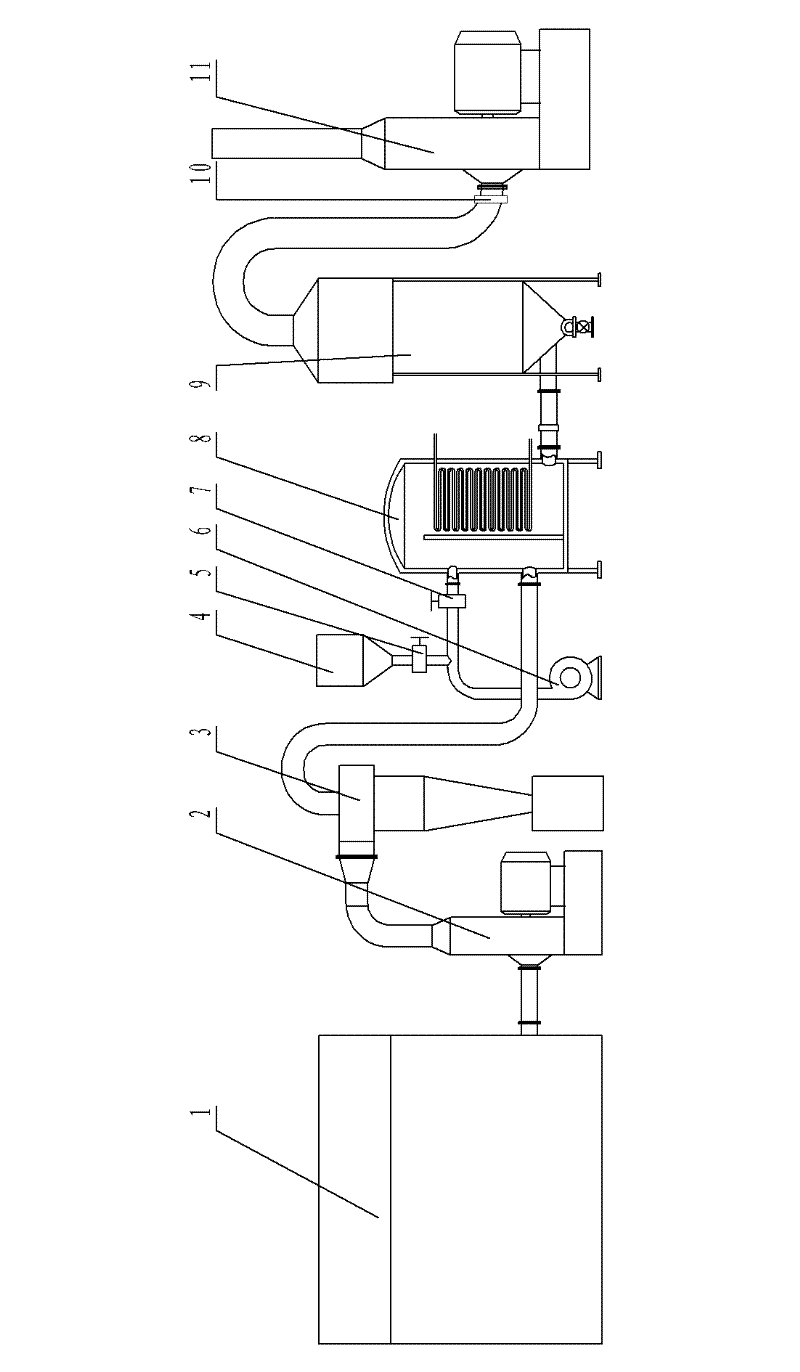
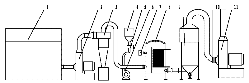
[0040] The flue gas dry desulfurization process method and the flue gas dry desulfurization system of the present invention are as follows figure 1 shown.

[0041]There is a coal-fired boiler 1 used for power generation and steam production. The exhaust port of the coal-fired boiler 1 is connected with a flue gas dedusting induced draft fan 2. The dust in the gas is separated from the flue gas, and the air outlet of the cyclone dust collector 3 is connected with the furnace of the waste heat recovery boiler 8, and the flue gas from which the soot has been removed is sent to the furnace of the waste heat recovery boiler 8; the outlet of the blower 6 passes through the pipe and the air flow The control valve 7 is connected to the upper inlet of the furnace of the waste heat recovery boiler 8, and the desulfu...

Embodiment 2

[0045] Example 2: 3,000 tons of coal with a sulfur content of 6% are burned daily, and the boiler air volume is 2.4x10 6 m 3 / h, the standard for emission into the air is 200mg / m 3 SO 2 . Adopt the system desulfurization of embodiment 1, the selection specification of waste heat boiler is 25 tons / hour, adopts 300 orders and contains calcium carbonate and is the consumption of 80% limestone powder and is 475 Kg / mim. Air consumption is 610 m 3 / mim, recovering 739.7 tons of calcium sulfate; producing 576 tons of steam; the cost of equipment is about 40 million yuan.

Embodiment 3

[0046] Example 3: Burn 3,000 tons of coal with a sulfur content of 6% per day, and the boiler air volume is 2.4x10 6 m 3 / h, the standard for emission into the air is 200mg / m 3 SO 2 . Adopt the system desulfurization of embodiment 1, the selection specification of waste heat boiler is 25 tons / hour, adopt the consumption of 300 order papermaking waste slag white mud that contains calcium carbonate to be 90% is 420 Kg / mim. Air consumption is 600 m 3 / mim, recover 735 tons of calcium sulfate; produce 560 tons of steam.


PUM

PropertyMeasurementUnit
Finenessaaaaaaaaaa

Abstract

The invention discloses a dry flue gas desulfurization process method and a dry flue gas desulfurization system thereof. The method comprises the following steps of: inputting flue gas after dust removal, air and a desulfurizer powder into a reaction chamber for mixing; reacting the desulfurizer with oxygen and sulfur dioxide in the flue gas to generate calcium sulfate; arranging a water cooler in an output passage of the reaction chamber; and absorbing heat in the flue gas and heat generated in desulfurization reaction by using the water cooler. Compared with the conventional dry desulfurization process method, the dry flue gas desulfurization process method has the advantage of solving the problems of unavailability of miscellaneous furnace slags and desulfurization products, secondary pollution caused by miscellaneous furnace slags and desulfurization products as well as reduced output power of a boiler caused by desulfurization reaction.

Description

technical field [0001] The invention relates to the technical field of exhaust gas treatment, in particular to a process method and system for separating and removing sulfur dioxide from combustion furnace flue gas. Background technique [0002] At present, the process methods for separating sulfur dioxide from the flue gas of the combustion furnace can be roughly divided into two types: wet desulfurization and dry desulfurization. The desulfurization slurry is in full contact with the flue gas in the flue gas by spraying, so that the desulfurizer in the slurry reacts with the sulfur dioxide in the flue gas to obtain unstable sulfite, and then through aeration, the sulfite Converted to sulfate. This method can control the desulfurization effect, but due to the low rate of sulfur dioxide in the slurry, in order to make the desulfurizer in the slurry fully react with the sulfur dioxide in the flue gas, it is usually necessary to add the desulfurization slurry to the flue gas m...

Claims


Application Information

Patent Timeline
IPC IPC(8): B01D53/83B01D53/50F23J15/00
Inventor 莫沙纱韦懿非江学艺
Owner 莫沙纱
Why Eureka
Try Eureka