Supercharge Your Innovation With Domain-Expert AI Agents!

Vertical water tank wire drawing machine

The utility model relates to a water tank wire drawing machine and a vertical technology, which is applied in the field of the vertical water tank wire drawing machine, and can solve the problems of low safety performance, high maintenance difficulty, long auxiliary time, etc., and achieves safe and convenient operation, improved drawing passes, and compact structure. Effect

Inactive Publication Date: 2012-02-29
JIANGSU GAOHE INTELLIGENT EQUIP CO LTD
View PDF4 Cites 6 Cited by
  • Summary
  • Abstract
  • Description
  • Claims
  • Application Information

AI Technical Summary

Problems solved by technology

[0002] At present, domestic water tank wire drawing machines are mostly flip-type water tank wire drawing machines. Drawing, tension, and wire take-up are independent of each other, occupying a large area, and inconvenient to operate and maintain.
The wire drawing machine for drawing steel wire mostly adopts horizontal water tank wire drawing machine with 21 passes or 23 passes. Due to the limitation of drawing passes, it is impossible to realize the thinner diameter steel wire required in the market in terms of technology. For example, drawing high-carbon thick steel wires of φ2.8mm or low-carbon thick steel wires to thin steel wires of φ0.11mm cannot be completed with existing wire drawing machines; moreover, it is difficult to thread wires into horizontal water tanks, and the auxiliary time is too long; in addition, the old-fashioned The drawing design of the water tank is open, and the safety performance is not high; because all the motors, transmission parts, and drawing tower wheels are installed on the same turning box, the stability of the equipment is not high, and the maintenance is difficult.

Method used


Image

  • Vertical water tank wire drawing machine
  • Vertical water tank wire drawing machine
  • Vertical water tank wire drawing machine

Examples


Embodiment Construction

[0022] The present invention will be further described below in conjunction with the accompanying drawings and embodiments.

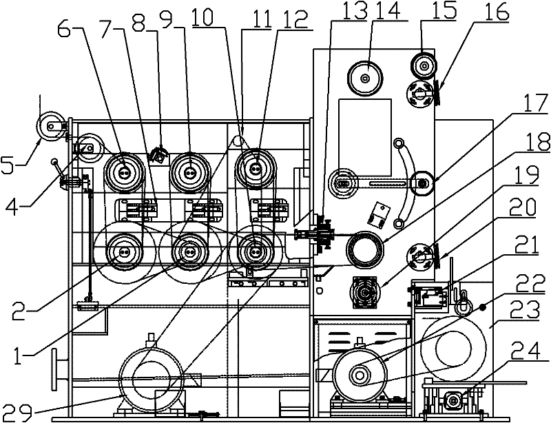
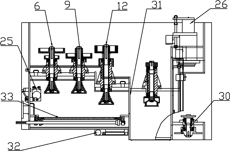
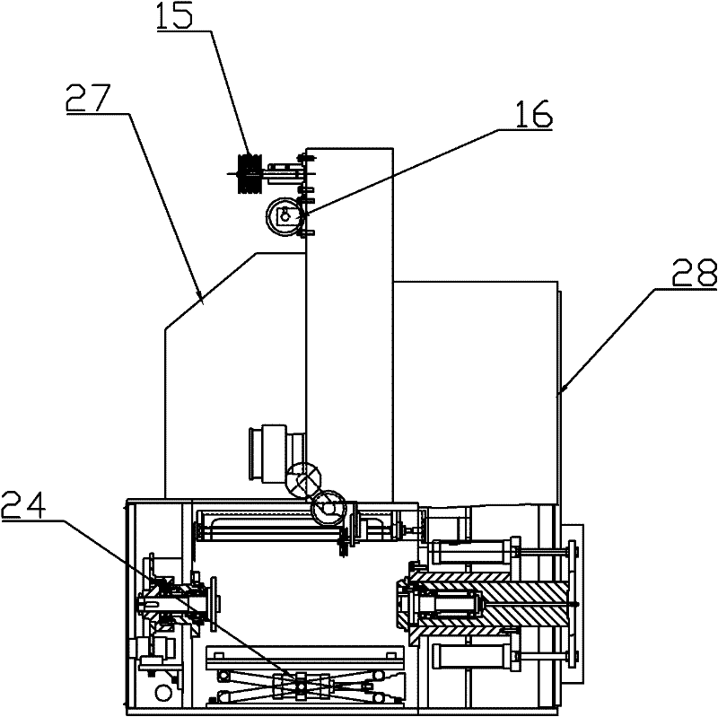
[0023] combine figure 1 , figure 2 with image 3 As shown, in this embodiment, the vertical water tank wire drawing machine includes several tower pulleys and corresponding wire drawing dies, a fine drawing die 13, a meter counting device 19, a traction wheel 18, a tension device 17, several wire passing devices, and a wire arranging device 17. Power device 29 and transmission device, the water tank wire drawing machine also includes a box body fixedly connected with the wire drawing machine frame, the tower pulley, the wire drawing die, the meter wheel, the traction wheel, the tension device, and several wire passing wheels The device, cable arrangement, power device and transmission device are all set in the box; the tower wheel includes three groups of tower wheels arranged in sequence, that is, the first tower wheel group (tape wheel group I), th...


PUM


Abstract

The invention discloses a vertical water tank wire drawing machine, which comprises a plurality of cone pulleys and corresponding wire drawing dies, a finishing die, a meter counter, a traction wheel, a tension device, a plurality of wire passing devices, a wire discharging device, a power device and a transmission device, wherein the cone pulleys are divided into a cone pulley group I, a cone pulley group II and a cone pulley group III; each cone pulley group comprises two cone pulleys which correspond to each other vertically, and are arranged on a lower driving shaft and an upper driven shaft; each cone pulley is provided with eight drawing grooves; a die frame is arranged between two cone pulleys of each cone pulley group; eight-pass wire drawing dies are arranged in the die frame corresponding to the drawing grooves of the cone pulleys; the diameters of the wire drawing dies are arranged from large to small; the finishing die is arranged corresponding to the cone pulley group III; and the aperture of the finishing die is the final diameter of the required finished steel wire. The drawing passes are increased, and the vertical water tank wire drawing machine is suitable for drawing thin steel wires, and has the advantages of short wire passing time, high startup safety, compact of whole machine, small floor area and contribution to operation and maintenance.

Description

technical field [0001] The invention relates to the technical field of metal wire processing equipment, in particular to a vertical water tank wire drawing machine. Background technique [0002] At present, most domestic water tank wire drawing machines are flip-type water tank wire drawing machines. The wire drawing, tension and wire take-up are independent of each other, occupy a large area, and are inconvenient to operate and maintain. The wire drawing machine for drawing steel wire mostly adopts horizontal water tank wire drawing machine with 21 passes or 23 passes. Due to the limitation of drawing passes, it is impossible to realize the thinner diameter steel wire required in the market in terms of technology. For example, drawing high-carbon thick steel wires of φ2.8mm or low-carbon thick steel wires to thin steel wires of φ0.11mm cannot be completed with existing wire drawing machines; moreover, it is difficult to thread wires into horizontal water tanks, and the auxi...

Claims


Application Information

Patent Timeline
IPC IPC(8): B21C1/04
Inventor 朱韵琴庄超陈雨峰胡贻军
Owner JIANGSU GAOHE INTELLIGENT EQUIP CO LTD
Features
  • R&D
  • Intellectual Property
  • Life Sciences
  • Materials
  • Tech Scout
  • Unparalleled Data Quality
  • Higher Quality Content
  • 60% Fewer Hallucinations
Learn More