Eureka AIR delivers breakthrough ideas for toughest innovation challenges, trusted by R&D personnel around the world.

Aerogenerator cable mandrel

A technology for wind turbines and cable cores, which is applied to wind turbine components, wind engines, wind power generation, etc., and can solve problems such as the influence of shaft rotation

Active Publication Date: 2012-02-29
CRRC YONGJI ELECTRIC CO LTD
View PDF4 Cites 4 Cited by
  • Summary
  • Abstract
  • Description
  • Claims
  • Application Information

AI Technical Summary

Problems solved by technology

[0003] In order to solve the problem that the control cable is affected by the rotation of the rotating shaft when passing through the rotating shaft, the present invention provides a wind power generator cable mandrel

Method used


Image

  • Aerogenerator cable mandrel
  • Aerogenerator cable mandrel
  • Aerogenerator cable mandrel

Examples


Embodiment Construction

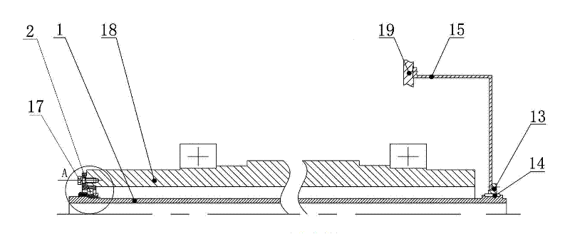
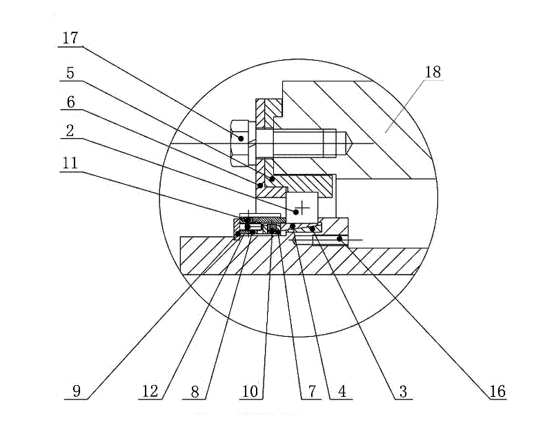
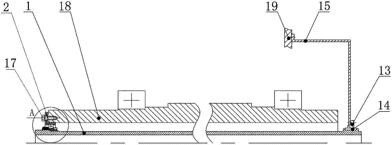
[0011] The wind power generator cable mandrel includes a mandrel 1; a sealed bearing 2 is installed at the front end of the mandrel 1; a tapered expansion sleeve is provided between the inner ring of the sealed bearing 2 and the outer surface of the mandrel 1, and the tapered expansion sleeve includes an inner The collar 3 and the outer collar 4, the inner collar 3 is socketed on the outer surface of the mandrel 1, the outer collar 4 is socketed between the outer surface of the inner collar 3 and the inner ring of the sealed bearing 2; the outer ring of the sealed bearing 2 is socketed There is a bearing seat 5, and the outer end surface of the bearing seat 5 is equipped with an annular gland 6; the front end of the mandrel 1 is respectively sleeved with a small nut 7, a large nut 8, and a spring retaining ring 9 for the shaft; the inner end surface of the small nut 7 is connected to the tapered The outer end surface of the expansion sleeve is in contact, the inner end surface ...


PUM


Abstract

The invention relates to a cable mandrel, and concretely relates to an aerogenerator cable mandrel. A problem that a control cable is influenced by the rotation of a pivot when the control cable traverses the pivot is solved in the invention. The aerogenerator cable mandrel is characterized in that: the aerogenerator cable mandrel comprises a mandrel; the front end of the mandrel is provided witha sealed bearing; a tapered expansion sleeve is arranged between the inner ring of the sealed bearing and the outer surface of the mandrel, the tapered expansion sleeve comprises an inner collar and an outer collar, the inner collar is sleeved on the outer surface of the mandrel, the outer collar is sleeved between the outer surface of the inner collar and the inner ring of the sealed bearing; a small nut, a large nut and a spring retaining ring for a shaft are respectively sleeved on the front end of the mandrel; and the rear end of the mandrel is provided with a sliding seat, and a clearance fit is arranged between the sliding seat and the outer surface of the rear end of the mandrel. The aerogenerator cable mandrel of the invention, which allows the problem that the control cable is influenced by the rotation of the pivot when the control cable traverses the pivot to be effectively solved, is suitable for the arrangement of the control cable in a high power permanent magnet semi-direct driven synchronous generator set.

Description

technical field [0001] The invention relates to a cable mandrel, in particular to a wind power generator cable mandrel. Background technique [0002] In the high-power permanent magnet semi-direct drive synchronous wind turbine unit, due to structural requirements, the control cable of the system needs to pass between the gearbox, the coupling and the shaft of the generator. When the unit is working, the rotating shaft rotates with the output shaft of the gearbox and the coupling, but the control cable is not allowed to rotate to prevent the control cable from being twisted, thereby affecting the safety of the control cable. Therefore, in order to ensure that the rotating shaft and the control cable do not interfere with each other, it is necessary to invent a brand-new mandrel structure to solve the problem that the control cable is affected by the rotation of the rotating shaft when passing through the rotating shaft. Contents of the invention [0003] In order to solve...

Claims


Application Information

Patent Timeline
Patent Type & Authority Applications(China)
IPC IPC(8): F16C35/08F16C41/00F16L3/06F03D11/00
CPCY02E10/72
Inventor 俞文斌钟绍辉崔皓石永进黄熙
Owner CRRC YONGJI ELECTRIC CO LTD
Why Eureka
Eureka Blog
Learn More