
Multi-picture image decoding display method and video monitoring terminal

A technology of video monitoring and image decoding, applied in image communication, closed-circuit television system, electrical components, etc., can solve the problems that users cannot browse the screen in time according to actual needs, the processing speed of CPU is reduced, and the speed and quality of decoding display are affected. Achieve the effect of clear and smooth picture, reduce decoding consumption, and resolve consumption conflicts

Active Publication Date: 2014-06-11
HANGZHOU HIKVISION DIGITAL TECH
View PDF5 Cites 0 Cited by
  • Summary
  • Abstract
  • Description
  • Claims
  • Application Information

AI Technical Summary

Problems solved by technology

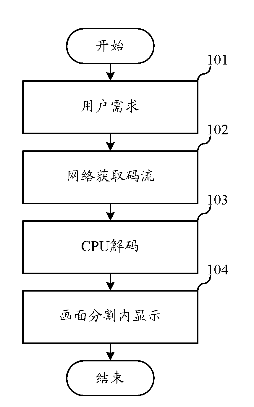
[0004] However, the inventors of the present invention have found that in the prior art, with the high-definition of the video surveillance industry, more and more high-definition videos have entered the scope of management, and the decoding of high-definition videos requires a powerful CPU. With continuous growth, the number of images that need to be decoded and displayed continues to increase, which will reduce the CPU processing speed, affect the speed and quality of decoding and display, and cause users to be unable to browse the screen in time according to actual needs

Method used


Image

  • Multi-picture image decoding display method and video monitoring terminal
  • Multi-picture image decoding display method and video monitoring terminal
  • Multi-picture image decoding display method and video monitoring terminal

Examples


Embodiment Construction

[0029] In the following description, many technical details are proposed in order to enable readers to better understand the application. However, those skilled in the art can understand that without these technical details and various changes and modifications based on the following implementation modes, the technical solution claimed in each claim of the present application can be realized.

[0030] In order to make the purpose, technical solution and advantages of the present invention clearer, the following will further describe the implementation of the present invention in detail in conjunction with the accompanying drawings.

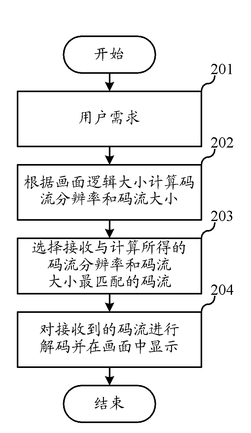
[0031] The first embodiment of the present invention relates to a method for decoding and displaying images of a video surveillance terminal. figure 2 It is a schematic flowchart of the method for decoding and displaying images of the video monitoring terminal.

[0032] Specifically, as figure 2 As shown, the method for decoding and displaying...


PUM


Abstract

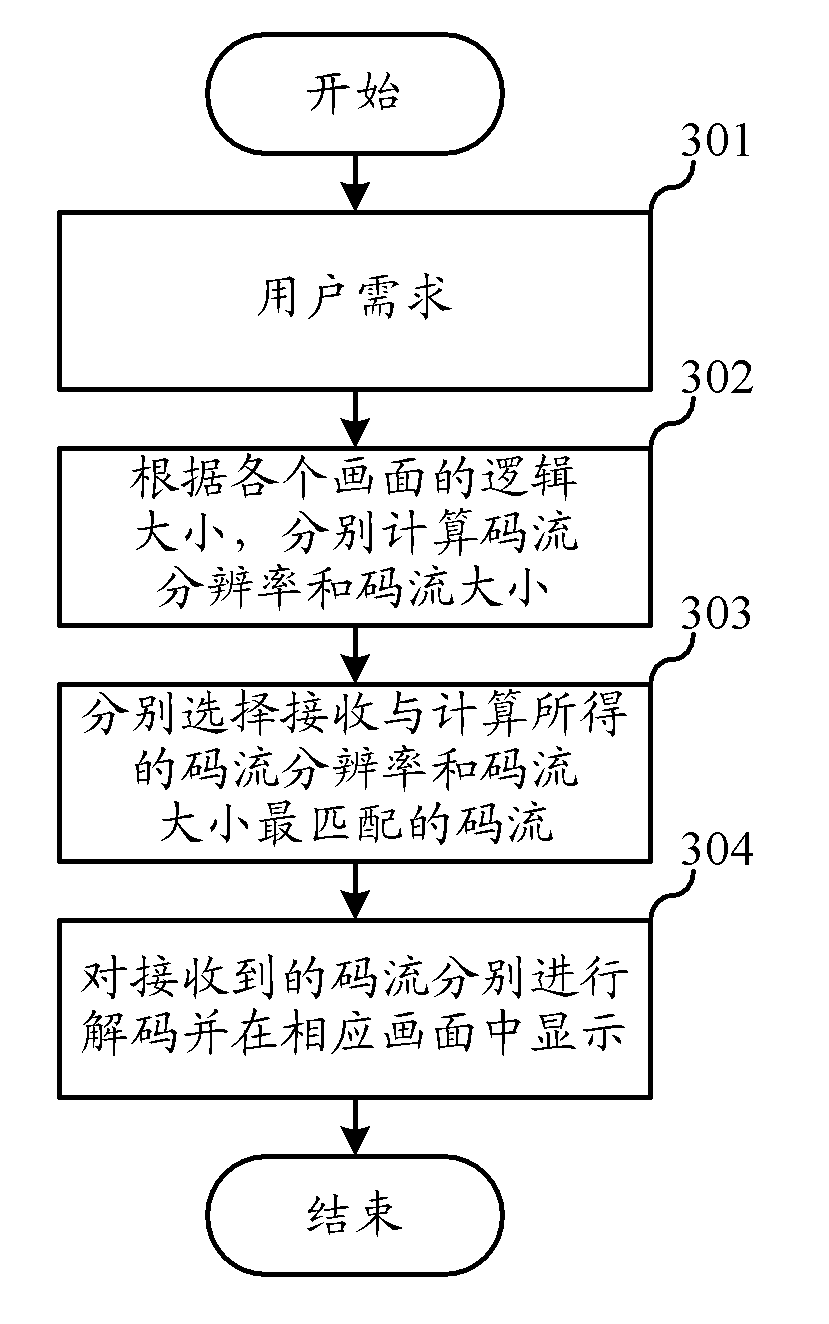
The invention relates to the field of video monitoring, and discloses a multi-picture image decoding display method and a video monitoring terminal. By the method and the terminal, an image is played back by selecting a proper code stream according to the logic size of the image, so the consumption of a central processing unit (CPU) in the video decoding of the terminal is reduced, and the definition and smoothness of the image are further ensured. Particularly for multi-picture splitting conditions, the effect of reducing the consumption of the CPU is more remarkable.

Description

technical field [0001] The invention relates to the field of video monitoring, in particular to a technique for decoding and displaying images of a video monitoring terminal. Background technique [0002] At present, in the video surveillance industry, the screen segmentation mode is generally used, and the performance of the Central Processing Unit ("CPU") of the personal computer (Personal Computer, "PC") is increasingly high, and multiple images are decoded and displayed at the same time. Realize the functions of contrast monitoring, synchronous monitoring and tracking monitoring between images. Screen segmentation refers to dividing the display screen into multiple display blocks for image decoding and display within the logical range according to the logical dot matrix of the display screen at the application software layer. [0003] In the multi-image decoding and display mode of realizing picture division, the prior art mainly adopts such as figure 1 The method show...

Claims


Application Information

Patent Timeline
Patent Type & Authority Patents(China)
IPC IPC(8): H04N7/18H04N21/234
Inventor 余家骝张小媛
Owner HANGZHOU HIKVISION DIGITAL TECH
Learn More