Ram guiding apparatus of machine tool

A technology of guiding device and ram, which is applied in metal processing machinery parts, metal processing equipment, manufacturing tools, etc., can solve the problems of heavy cutting ability, low machining accuracy, and many moving parts, so as to improve cutting ability and reduce Vibration, improving the effect of the machined surface

Inactive Publication Date: 2012-02-29
杉山明
View PDF11 Cites 0 Cited by
  • Summary
  • Abstract
  • Description
  • Claims
  • Application Information

AI Technical Summary

Problems solved by technology

However, on the contrary, there are more movable parts, and the actual heavy-duty cutting capability and machining accuracy are lower than those of fixed beams.

Method used


Image

  • Ram guiding apparatus of machine tool
  • Ram guiding apparatus of machine tool
  • Ram guiding apparatus of machine tool

Examples


Embodiment Construction

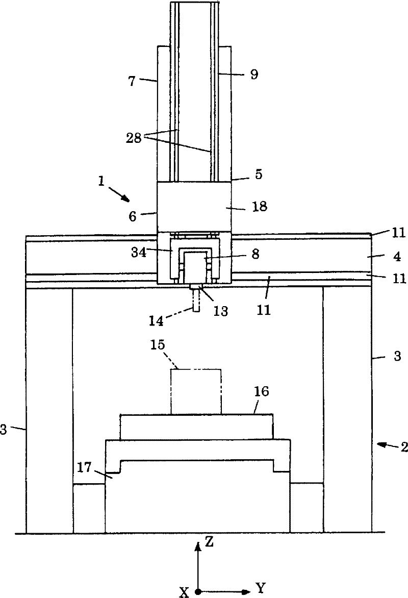
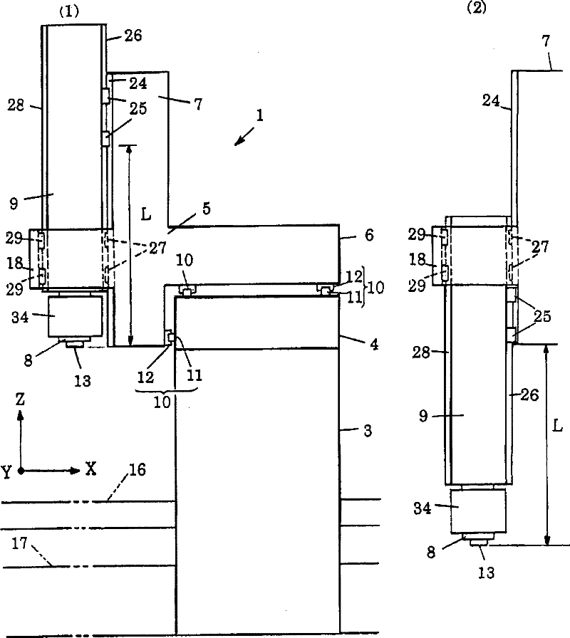
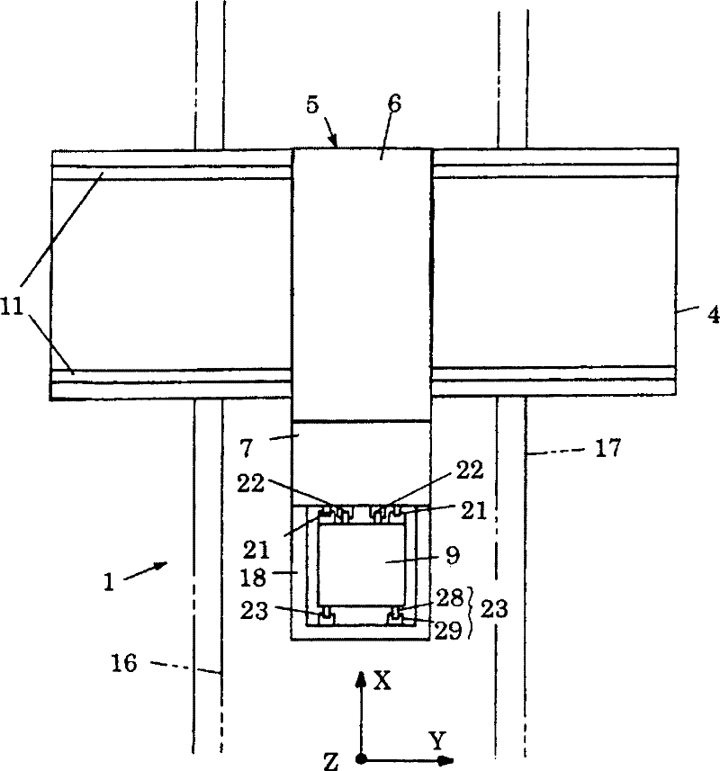
[0080] Figure 1 to Figure 5 The ram guide device 1 of the machine tool according to the present invention is shown. In these figures, the ram guide 1 of the machine tool presupposes a gantry machine tool 2 . The gantry machine tool 2 is, for example, a gantry machining center. A horizontal beam 4 is erected on the left and right columns 3 , and the column 3 and the beam 4 form a gantry portion for holding the cross saddle 5 .

[0081] The cross saddle 5 is cross-shaped when viewed from the side, and is composed of a horizontal portion 6 in the front-rear direction, that is, the X-axis direction, and a vertical portion 7 that is a direction that crosses the horizontal portion, that is, the Z-axis direction. The ram 9 for supporting the machining head 8 is provided movably in the direction, and is movably held in the vertical direction, that is, the Z-axis direction on the front side.

[0082] As an example, the cross saddle 5 is movably guided in the Y-axis direction by two ...


PUM


Abstract

A support configuration with which a ram can be reciprocated by a saddle is improved, thereby suppressing the vibration of the ram and the chattering phenomenon of a cutting tool, improving a heavy cut, upgrading a finished surface, extending the life of the cutting tool, and preventing the cutting tool from being broken. A ram guiding apparatus (1) of a machine tool is built in a portal type machine tool (2) and has a cross saddle (5) having a cross shape when viewed from a side and being freely movable along a horizontal cross beam (4). The cross saddle (5) has a box (18), the top and bottom surfaces of which are open and which is provided in front of the horizontal portion. A first linear guide (21), a second linear guide (22), and a third linear guide (23), which serve inside the box (18) as linear guides for a ram vertical movement, guide a ram (9) so as to be freely movable only in the vertical direction.

Description

technical field [0001] The present invention relates to a device for guiding a ram for tool holding in the vertical direction through a saddle in a gantry machine tool. Background technique [0002] Patent Document 1 and Patent Document 2 show a gantry machine tool. A gantry machine tool, such as a gantry machining center, constructs a gantry by erecting a horizontal beam on the left and right columns, and the beam keeps the saddle freely movable in the longitudinal direction of the beam. The saddle is mounted on the front of the beam as a front-mounted type, or mounted on the top of the beam as a top-mounted type, and is movably held by the beam. [0003] The front-mounted saddle or the top-mounted saddle supports the ram in a vertically reciprocating state at the front position of the gantry machining center, and holds, for example, 5-axis control at the lower end of the ram. machining head, or a corner machining head with 5-axis control. The tools necessary for machini...

Claims


Application Information

Patent Timeline
Patent Type & Authority Applications(China)
IPC IPC(8): B23Q1/70B23Q1/56B23Q1/58
CPCB23Q1/012B23Q1/017Y10T409/306776Y10T409/307112Y10T409/307672Y10T409/307728Y10T409/309576
Inventor 杉山明
Owner 杉山明
Why Eureka
Try Eureka