Electrically driven vehicle

A technology for electric vehicles and electric motors, which is applied to electric vehicles, electric scooters, motor vehicles, etc., can solve the problems of generating rotational resistance, difficult to start, and the installation space cannot use electric motors, and achieves the effect of a simple structure.

Active Publication Date: 2014-01-01
HONDA MOTOR CO LTD
View PDF6 Cites 0 Cited by
  • Summary
  • Abstract
  • Description
  • Claims
  • Application Information

AI Technical Summary

Problems solved by technology

[0007] However, as the characteristics of the motor, it is known that the rotation control after the start of rotation is easy, but the rotation cannot be started from a state where a load larger than the starting torque of the motor is applied.
Although the above-mentioned problems can be solved by making the output of the electric motor sufficiently large, in small vehicles such as two-wheeled vehicles, especially in the swing arm that rotatably supports the rear wheel and is installed on the frame freely, the electric motor of the electric motor is accommodated. In a two-wheeled vehicle, a motor that is too large cannot be used due to the increase in installation space and weight, and the above-mentioned disadvantages sometimes occur
[0008] In the electric vehicle described in Patent Document 1, since the electric motor and the drive wheels are directly connected through the reduction gear set, when the vehicle is heavy or on a slope, etc., it may be difficult to start due to the above-mentioned characteristics of the electric motor. possibility of
In addition, when the vehicle is propelled without the motor generating rotational driving force, there is also the problem of generating rotational resistance of the motor and making the propulsion heavy.
[0009] In addition, in the electric vehicle described in Patent Document 2, since the one-way clutch is provided, there is no rotational resistance when pushing in the forward direction of the vehicle. When reversing, since the one-way clutch connects the rear wheel to the motor, there is a problem of rotation resistance
In addition, when driving on a slope or the like, there is a problem similar to that of the electric vehicle described in Patent Document 1.

Method used


Image

  • Electrically driven vehicle
  • Electrically driven vehicle
  • Electrically driven vehicle

Examples


Embodiment Construction

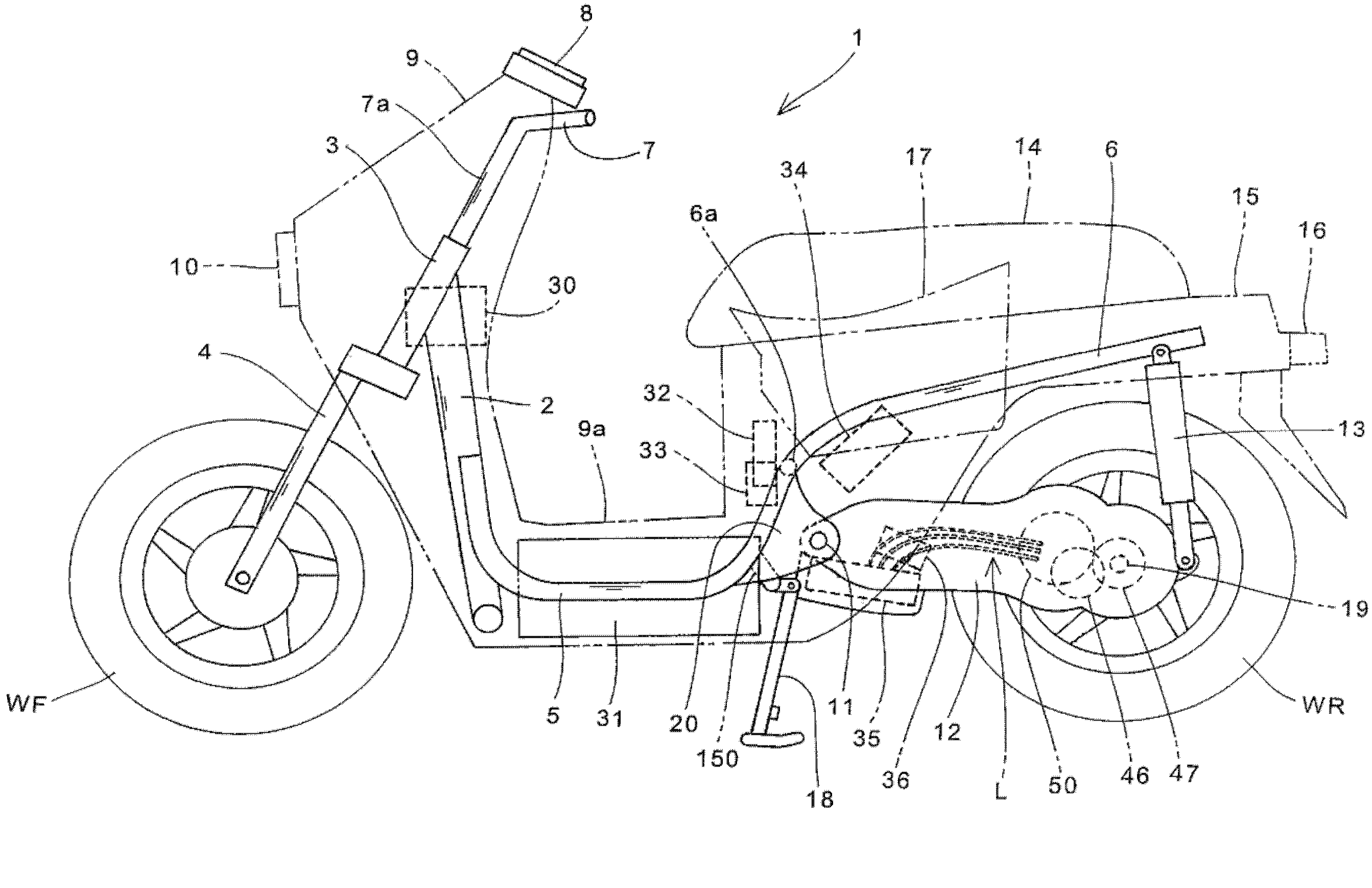
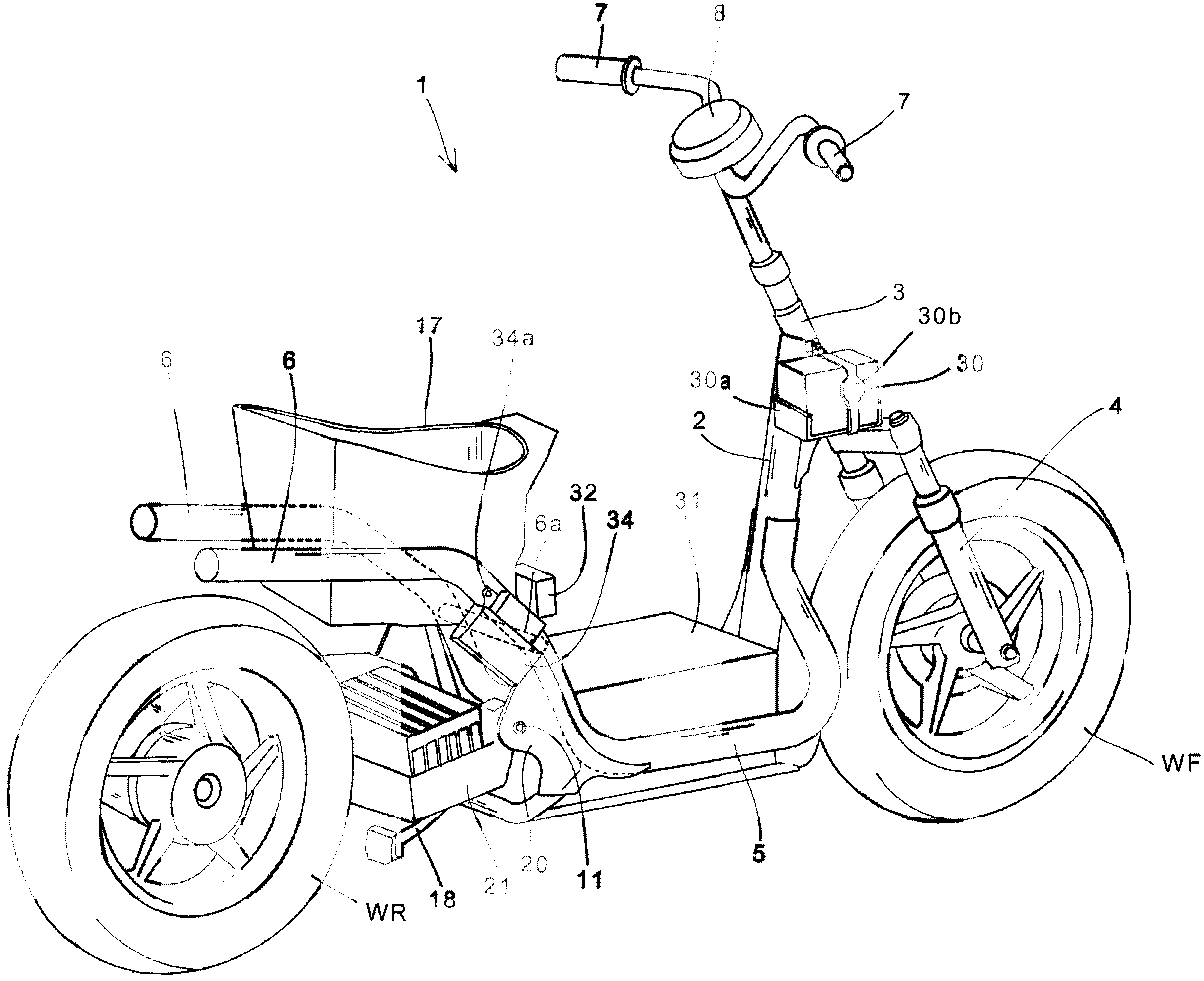
[0036] Hereinafter, preferred embodiments of the present invention will be described in detail with reference to the drawings. figure 1 It is a side view of the electric vehicle 1 according to one embodiment of the present invention. in addition, figure 2 It is a rear perspective view of the electric vehicle 1 with exterior parts removed. The electric vehicle 1 is a scooter-type motorcycle with a low floor, and the rear wheels WR are driven by the rotational driving force of the electric motor 50 built in the swing arm 12 . In addition, the high-voltage battery 31 that supplies electric power to the electric motor 50 is charged by connecting an external power supply to a charging port (not shown) provided in the vehicle body.

[0037] A head pipe 3 that rotatably pivotally supports a steering rod 7 a is coupled to a front side end portion of the main frame 2 . A steering handle 7 is attached to the upper portion of the steering rod 7a, and a pair of left and right front fo...


PUM


Abstract

Provided is an electric vehicle that is easy to start to move even when there is load applied, and which does not generate rotational resistance of the electric motor when the vehicle is push-walked. A connection / disconnection mechanism is provided between the electric motor (50) and the speed reducing mechanism (70) to switch transmission of the rotating driving force from a disabled state to an enabled state when the electric motor (50) rotates at a predetermined rotation speed or more. The connection / disconnection mechanism is a centrifugal clutch (40). The swing arm (12) is configured as a cantilever-type, supported only at the left side in the vehicle width direction, so that the centrifugal clutch (40), the electric motor (50), and the speed reducing mechanism (70) are arranged in this order, from the left side in the vehicle width direction.

Description

technical field [0001] The present invention relates to electric vehicles, and more particularly to electric vehicles in which drive wheels are driven by electric motors. Background technique [0002] Conventionally, electric vehicles are known in which drive wheels are driven by electric motors. [0003] Patent Document 1 discloses an electric vehicle in which an electric motor is disposed inside a swing arm that rotatably supports rear wheels, and a reduction gear set that performs one-stage reduction is provided between the electric motor and an axle of the rear wheels. [0004] Also, Patent Document 2 discloses an electric vehicle in which a motor is arranged inside a swing arm that rotatably supports rear wheels, and a reduction gear set and a one-way clutch are provided between the motor and the axle of the rear wheels. [0005] Patent Document 1: Japanese Patent Laid-Open No. 2004-358982 [0006] Patent Document 2: Japanese Patent Laid-Open No. 2003-127966 [0007]...

Claims


Application Information

Patent Timeline
Patent Type & Authority Patents(China)
IPC IPC(8): B60L15/20B60K7/00B62K25/20B62M7/12F16D43/14
CPCB60K17/043B62K25/005B62M7/12B62K2202/00B60K2007/0038Y02T10/7258B60Y2200/126F16D43/18B62K2204/00B60K7/0007B60L2200/24B60W2300/365B60L15/2054B60L2200/12Y02T10/72Y02T10/64B60L15/20B60K7/00B62K25/20
Inventor 味村政秀新妻桂一郎铃木仁
Owner HONDA MOTOR CO LTD
Why Eureka
Try Eureka