
Valves having ceramic trim with protected shut-off surfaces

A closing member, non-ceramic technology, used in the field of control valves, which can solve problems such as valve plug and valve seat cracking, crushing or collapsing

Active Publication Date: 2012-02-29
FISHER CONTROLS INT LLC
View PDF5 Cites 6 Cited by
  • Summary
  • Abstract
  • Description
  • Claims
  • Application Information

AI Technical Summary

Problems solved by technology

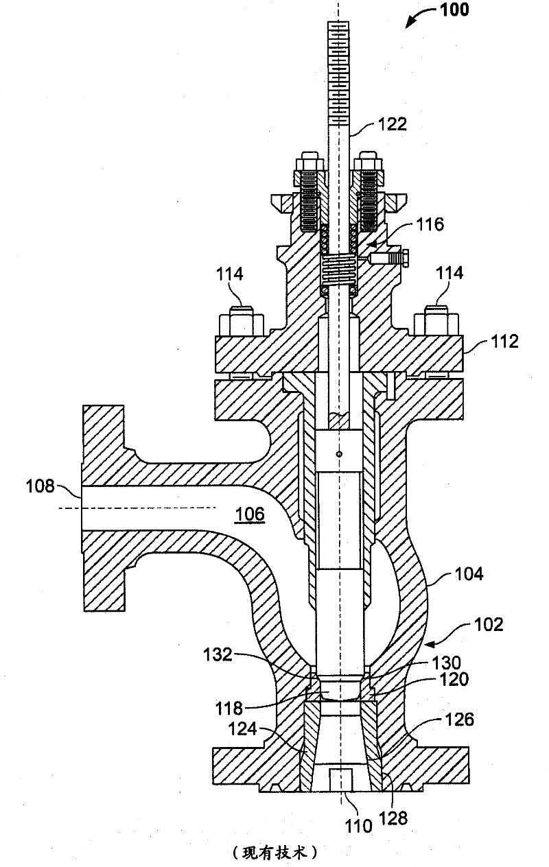
Under such high loads, the ceramic plug and / or seat can crack, crumble or collapse

Method used


Image

  • Valves having ceramic trim with protected shut-off surfaces
  • Valves having ceramic trim with protected shut-off surfaces
  • Valves having ceramic trim with protected shut-off surfaces

Examples


Embodiment Construction

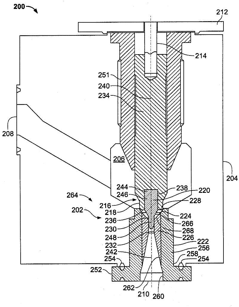
[0016] In general, the example valve trim arrangement described here can be used with heavily aggressive process fluids, such as process fluids (such as hydrogen fluids) that contain entrained particles (such as ceramic catalysts) that often damage or corrode traditional valve trim parts. The example valve trim apparatus described herein significantly increases the operating life of the valve trim compared to the conventional valve trim.

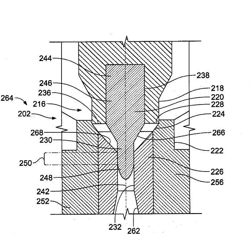
[0017] More specifically, the example valve trim apparatus described herein provides a throttling portion or function that is separate from a closing portion or function. Still further, the example trim device diverts a significant portion of the pressure differential of the process fluid to the restricted portion of the trim device and, thus, minimizes the differential pressure across the closed portion of the trim device . Additionally, relatively large seat loads or thrusts may be applied to the closing portion of the trim device while ...


PUM


Abstract

Valve trim apparatus (202) having ceramic trim (210) with protected shut-off surfaces are described. An example valve trim apparatus includes a valve seat (222) composed of a non- ceramic material and having a sleeve insert (226) composed of a ceramic material. A closure member (216) has a primary flow control member (218) and a secondary flow control member (220). The secondary flow control member is composed of a ceramic material and fitted within a cavity (238) of the closure member (216). The primary flow control member sealingly engages the non- ceramic material of the valve seat and the secondary flow control member moves within an aperture (232) of the sleeve insert to modulate a fluid flow through the valve seat as the primary flow control member disengages from the non -ceramic material of the valve seat.

Description

[0001] Cross References to Related Applications [0002] This patent claims the benefit of U.S. Provisional Application Serial No. 61 / 315,717, filed March 19, 2010, entitled Valves Having Ceramic Internals with Protected Shutoff Surfaces, which is incorporated by reference in its entirety merged here. technical field [0003] This patent relates generally to control valves and, more particularly, to a valve with a ceramic trim with a protected throttling surface. Background technique [0004] Control valves are commonly used in process control plants or systems to control the flow of process fluids. In general, the control valve typically includes a valve trim assembly or device that includes a valve plug (eg, a metal valve plug) and a valve seat (eg, a metal seat ring) that are positioned In the fluid path, to control the fluid flow through the channel between the inlet and the outlet. A valve stem or shaft couples the valve plug to an actuator, eg, a pneumatic actuator...

Claims


Application Information

Patent Timeline
Patent Type & Authority Applications(China)
IPC IPC(8): F16K47/04
CPCF16K47/04F16K1/42
Inventor J·W·里查德松R·L·贝克斯E·J·梅尔沃尔德C·J·哈蒙德
Owner FISHER CONTROLS INT LLC
Learn More