Pushing device for inside and outside direction and rotary direction of tool in gear processor

A technology of rotating direction and pushing device, applied in the field of machinery, can solve the problems of poor mechanical work stability, difficult manufacturing, insufficient rigidity, etc., and achieve the effects of safe and reliable work, improved machining accuracy, and stable work.

Inactive Publication Date: 2012-03-07
NINGBO YINZHOU TAISHENG NUMERICAL CONTROL EQUIP
View PDF0 Cites 2 Cited by
  • Summary
  • Abstract
  • Description
  • Claims
  • Application Information

AI Technical Summary

Problems solved by technology

[0002] Among mechanical products, gear products account for the majority. Generally, the tool is fixed by the tool driving device in the gear processing machine, and then the tool is rotated by rotating the tool and the workpiece fixed on the worktable. The reciprocating motion is used to shape the workpiece into the required gear shape. Here, in the processing engineering, it is necessary to move in and out along the B-axis direction (inward and outward) and to rotate. The existing tool pushing device is structurally The shortcomings of the design problem are: insufficient rigidity, poor mechanical stability during work, which affects the machining accuracy and work efficiency of the gear, and at the same time, the space size and weight increase, and the manufacturing is also difficult, so it is necessary to move the existing tool device for improvement

Method used


Image

  • Pushing device for inside and outside direction and rotary direction of tool in gear processor
  • Pushing device for inside and outside direction and rotary direction of tool in gear processor
  • Pushing device for inside and outside direction and rotary direction of tool in gear processor

Examples


Embodiment Construction

[0012] The following are specific embodiments of the present invention and in conjunction with the accompanying drawings, the technical solutions of the present invention are further described, but the present invention is not limited to these embodiments.

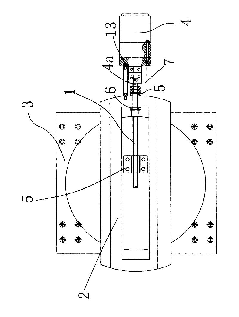
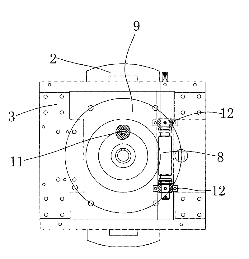
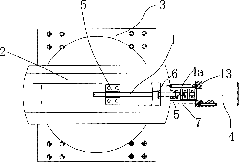
[0013] In the figure, screw mandrel 1; tool seat 2; slide plate 3; motor 4; output shaft 4a; nut seat 5; plane bearing 6; connecting plate 7; connecting sleeve 8; worm wheel 9; worm 10; washer 11; steel sleeve 12; Hexagon socket head cap screw 13.

[0014] like figure 1 As shown, the driving device in the gear processing machine in the internal and external directions and the rotating direction of the tool mainly drives the tool to move in the internal and external directions and the rotating direction, including the screw rod 1, the tool seat 2, the slide plate 3, the motor 4, the nut seat 5, and the slide plate 3 and the nut seat 5 are fixedly connected with the hexagon socket head screw 13, the knife seat 2 is installe...


PUM


Abstract

The invention belongs to the technical field of machinery, and provides a pushing device for the inside and outside direction and the rotary direction of a tool in a gear processor. The pushing device comprises a lead screw, a tool apron, a sliding plate, a motor and a nut seat, wherein the sliding plate and the nut seat are fixedly connected; the tool apron is installed on the sliding plate; the nut seat is arranged on the left part of the lead screw and is meshed with the lead screw; the right part of the lead screw is fixedly connected with the output shaft of the motor; the sliding plate is also provided with a worm gear and a worm; and the worm gear and the worm are meshed and drive the sliding plate to rotate. The pushing device has the advantages that the lead screw drives the sliding plate to move along the inside and outside direction, and the worm gear and the worm drive the sliding plate to rotate so as to drive the tool to process the gear. The whole device is stable, safe and reliable to work and is favorable for improving the machining precision of the gear, components have compact layout, and the technical defect in the prior art can be overcome.

Description

technical field [0001] The invention belongs to the technical field of machinery, and relates to a gear processing machine, in particular to a device for pushing the tool in the internal and external directions and the rotation direction of the gear processing machine. Background technique [0002] Among mechanical products, gear products account for the majority. Generally, the tool is fixed by the tool driving device in the gear processing machine, and then the tool is rotated by rotating the tool and the workpiece fixed on the worktable. The reciprocating motion is used to shape the workpiece into the desired gear shape. Here, in the processing engineering, it is necessary to move in and out along the B-axis direction (inward and outward) and to perform rotational motion. The existing tool pushing device is structurally The shortcomings of the design problem are: insufficient rigidity, poor mechanical stability during work, which affects the machining accuracy and work ef...

Claims


Application Information

Patent Timeline
Patent Type & Authority Applications(China)
IPC IPC(8): B23Q5/34B23Q5/40
Inventor 吕琦王伟雄
Owner NINGBO YINZHOU TAISHENG NUMERICAL CONTROL EQUIP
Why Eureka
Try Eureka