Construction method of steel pipe arch bridge

A construction method and technology for steel pipe arch bridges, applied to arch bridges, bridges, bridge materials, etc., can solve the problems of long-term occupation of waterways, high construction costs, and inconvenient construction, and achieve the effects of fast erection, efficient and safe construction, and convenient operation

Inactive Publication Date: 2012-03-07
中铁一局集团厦门建设工程有限公司
View PDF3 Cites 16 Cited by
  • Summary
  • Abstract
  • Description
  • Claims
  • Application Information

AI Technical Summary

Problems solved by technology

The above-mentioned construction method has the following disadvantages: except for the second closing section, the steel beams of other sections need to be

Method used


Image

  • Construction method of steel pipe arch bridge
  • Construction method of steel pipe arch bridge
  • Construction method of steel pipe arch bridge

Examples


Embodiment Construction

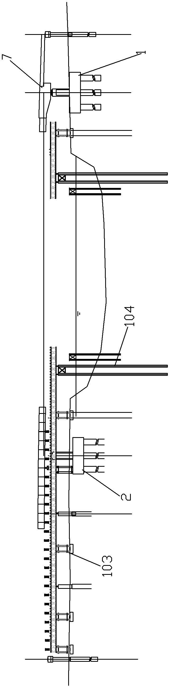
[0052] For a construction method of a steel pipe arch bridge, please refer to Figure 8 to Figure 16 ,it includes:

[0053] Step 1, constructing the first bridge pier 1 and the second bridge pier 2, and pouring the cast-in-place beam 7 on the first bridge pier 1; and, in this embodiment, the first approach bridge and the second approach bridge are also constructed, and the first approach bridge is connected The first pier, the second approach bridge connects to the second pier;

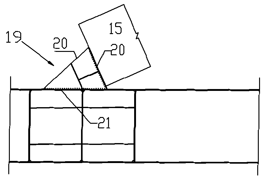
[0054] Step 2, on the side corresponding to the second pier 2, such as the second approach bridge, fix and assemble multiple sections of steel girders into a steel girder intermediate section 5, and assemble multiple sections of arch tubes into an arch tube intermediate section 15 on the second pier 2, The middle section of the steel beam 5 and the middle section of the arch tube 15 are combined to form the middle section of the arch beam 22, and the middle section of the arch tube 15 is located abo...


PUM


Abstract

The invention discloses a construction method of a steel pipe arch bridge, which comprises the following steps: step 1) constructing a first bridge pier and a second bridge pier and pouring a cast-in-place beam on the first bridge pier; step 2) fixedly splicing multiple sections of steel beams into a steel beam middle section on one side corresponding to the second bridge pier; step 3) transporting the steel beam middle section to a designed position, and enabling the two ends of the steel beam middle section to be respectively supported on the first bridge pier and the second bridge pier; step 4) pouring the cast-in-place beam on the second bridge pier; and step 5) respectively butting and folding two folding sections at the two ends of the middle section so as to form a main beam. The construction of the main body part of the main beam is completed on the land, thereby having the advantages of safety, high efficiency, short time occupied by a fairway and high construction precision.

Description

technical field [0001] The invention relates to a construction method of a steel pipe arch bridge. Background technique [0002] The construction method of the existing steel pipe arch bridge comprises: step 1, constructing the second bridge pier, and pouring cast-in-situ beams on the second bridge pier; step 2, installing and connecting the first closing section at the first bridge pier; step 3, setting up temporary supports on the waterway , welding the steel girder on the temporary support until the second pier; step 4, welding the steel girder on the second pier and the second closing section to form the main girder. Adopting the above-mentioned construction method has the following disadvantages: the steel girders of other sections except the second closing section need to be constructed on temporary supports, and the waterway must be occupied for a long time, which is inconvenient for construction and high in construction cost. Contents of the invention [0003] The...

Claims


Application Information

Patent Timeline
IPC IPC(8): E01D21/00E01D4/00E01D101/30
Inventor 李世清范学功李宏涛徐建宁刘帮新曾凡福解叶龙念家香张战通张军剑胡艳
Owner 中铁一局集团厦门建设工程有限公司
Why Eureka
Try Eureka