Oil tank and crane with same

An oil tank and oil suction oil filter technology, which is applied in the hydraulic field, can solve the problems of not realizing the oil tank, limited space, and inability to be used, and achieve the effect of avoiding air suction and prolonging the service life.

Inactive Publication Date: 2012-03-07
XUZHOU HEAVY MASCH CO LTD
View PDF7 Cites 3 Cited by
  • Summary
  • Abstract
  • Description
  • Claims
  • Application Information

AI Technical Summary

Problems solved by technology

[0010] image 3 and Figure 4 The structure of the fuel tank shown in the design idea is to remove the invalid volume of the fuel tank, and reduce the volume of the fuel tank as much as possible while meeting the requirements of the system, but the space saved is very limited and

Method used


Image

  • Oil tank and crane with same
  • Oil tank and crane with same
  • Oil tank and crane with same

Examples


Embodiment Construction

[0029] The core of the present invention is to provide an oil tank, which can not only store enough oil for the hydraulic system to prevent the oil pump from sucking, but also can make full use of the space on the construction machinery and arrange it reasonably. Another core of the present invention is to provide a crane with the above oil tank.

[0030] In order to enable those skilled in the art to better understand the solution of the present invention, the present invention will be further described in detail below in conjunction with the accompanying drawings and specific embodiments.

[0031] Please refer to Figure 5 A schematic structural view of a specific embodiment of the fuel tank provided by the present invention is shown.

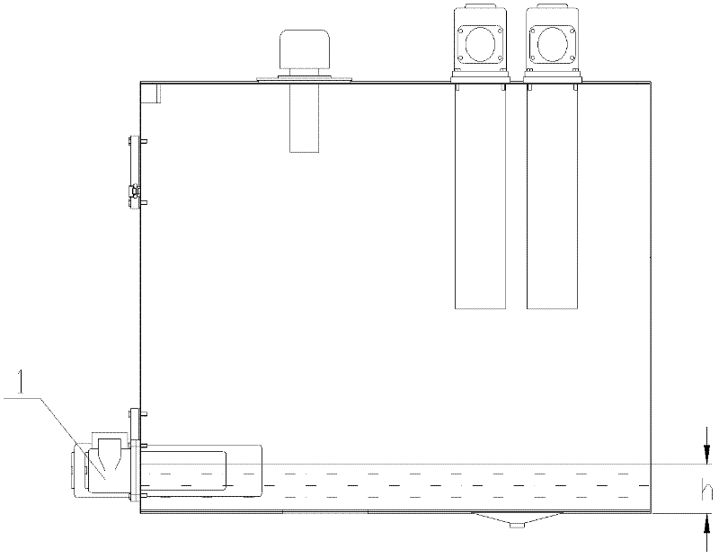
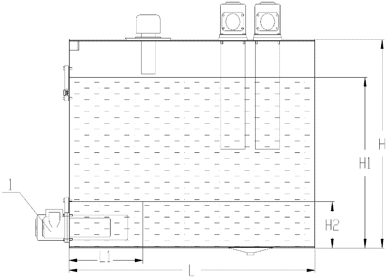
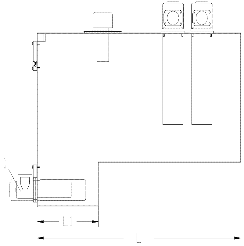
[0032] from Figure 5 As can be seen from the structural diagram of the specific embodiment of the shown oil tank, the oil tank includes a main tank body 10 and an oil suction filter 30 communicated with the main tank body 10, and the oil s...


PUM


Abstract

The invention discloses an oil tank, wherein the oil tank is provided with a main tank body, an oil pumping filter and a first auxiliary tank body, wherein the oil pumping filter is communicated with the main tank body; the first auxiliary tank body is arranged outside the main tank body and is communicated with the main tank body; the oil pumping filter is installed on the first auxiliary tank body; and the position of the first auxiliary tank body is lower than the lowest oil level of the liquid oil in the main tank body. The oil tank provided by the invention has the beneficial effects that the oil pumping filter installed on the first auxiliary tank body is enabled to be always immersed in the liquid oil, thereby ensuring that an oil pump always can pump oil and further effectively avoiding the phenomenon that all oil is pump up by the oil pump; and simultaneously, the first auxiliary tank body which is independent of the main tank body can be arranged flexibly according to the idle space on engineering machinery, the space on engineering machinery is utilized fully, and the more reasonable arrangement of the oil tank on engineering machinery is realized.

Description

technical field [0001] The invention relates to the field of hydraulic technology, in particular to an oil tank. In addition, the present invention also relates to a crane with the above-mentioned oil tank. Background technique [0002] The oil tank occupies an important position in the hydraulic system. It has the functions of storing the hydraulic oil required for the circulation of the hydraulic system, dissipating the heat generated when the system is working, and releasing the gas mixed in the hydraulic oil. One of the most important functions is In order to store the oil required for the circulation of the hydraulic system. [0003] In order to adapt to complex operation requirements, the number of components in the hydraulic system gradually increases, and the demand for oil volume also increases accordingly. In this case, more hydraulic oil needs to be stored, so a larger volume oil tank is required. [0004] However, since the various mechanisms in the hydraulic s...

Claims


Application Information

Patent Timeline
IPC IPC(8): F15B1/26
Inventor 冯文昌赵磊
Owner XUZHOU HEAVY MASCH CO LTD
Why Eureka
Try Eureka