

Automatic washing and dewatering combined device of rotary type mop
An automatic cleaning and combined device technology, which is applied in the direction of cleaning carpets, cleaning floors, cleaning equipment, etc., can solve the problems that the mop is difficult to align with the bucket cleaning positioning axis, consumes the user's physical strength, and is easy to deviate from the positioning axis, etc., to achieve aesthetics and practicality , reduce water consumption, safe and convenient operation
- Summary
- Abstract
- Description
- Claims
- Application Information
AI Technical Summary
Problems solved by technology
Method used
Image

Examples
Embodiment Construction
[0046] The present invention will be further described below in conjunction with the accompanying drawings and embodiments.
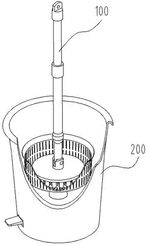
[0047] Such asfigure 1 , As shown in 6, the rotary mop automatic cleaning and dehydration combination device of the present invention is composed of a rotary mop 100 and a cleaning and dehydration bucket 200.
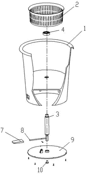
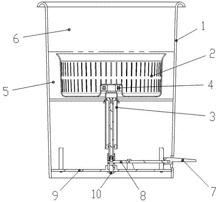
[0048] Such as figure 2 , 7, 12, and 14, the cleaning and dehydration barrel 200 includes: a barrel body 1 and a dehydration basket 2, the lower part of the barrel body 1 is the cleaning area 5, and the upper part is the dehydration area 6, and the dehydration basket 2 is placed in the washing area of the barrel body 2 5 or in the dehydration zone 6.
[0049] A lifting and fixing device for the dehydration basket, which is placed in the barrel body 1 and connected with the dehydration basket 2, is used to lift the dehydration basket 2, so that the dehydration basket 2 is in the cleaning area 5 at the bottom of the barrel body 1 when the mop i...
PUM
 Abstract
Description
Claims
Application Information