Riveting machine

A riveting machine and rivet technology, applied in the field of flywheel assembly equipment, can solve the problems of difficulty in guaranteeing riveting quality and low production efficiency, and achieve the effects of high assembly efficiency and high yield

Inactive Publication Date: 2012-03-14
厦门义胜自动化设备有限公司
View PDF7 Cites 39 Cited by
  • Summary
  • Abstract
  • Description
  • Claims
  • Application Information

AI Technical Summary

Problems solved by technology

[0002] The current riveting of the flywheel base and the flywheel shell is mostly manual operation, the production efficiency is low, and the riveting quality is difficult to guarantee

Method used


Image

  • Riveting machine
  • Riveting machine
  • Riveting machine

Examples


Embodiment Construction

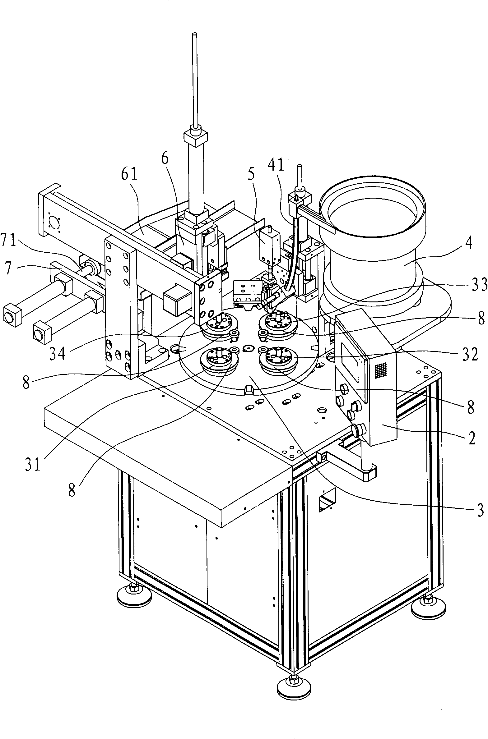
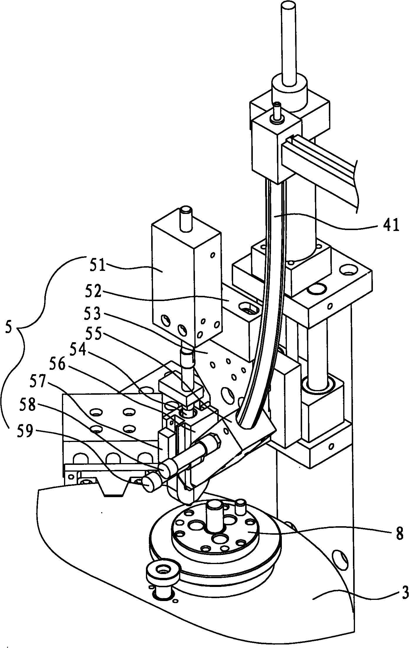
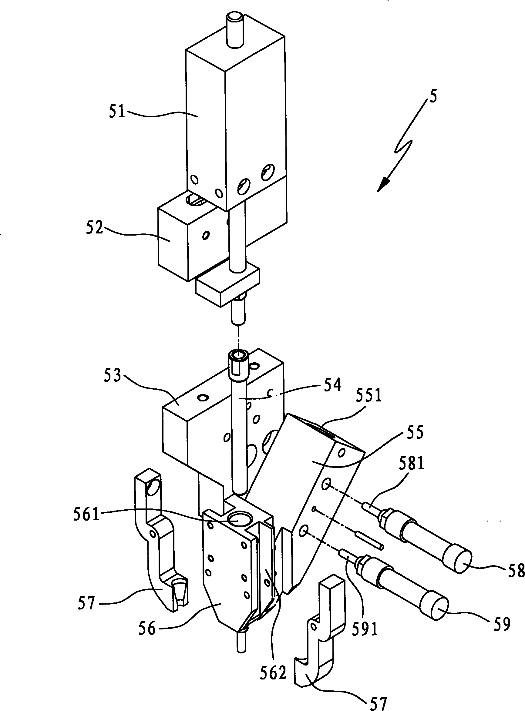
[0012] Such as figure 1 As shown, the present invention is a riveting machine, which is mainly composed of a machine platform 1, a control panel 2, a station turntable 3, a vibrating mechanism 4, a riveting mechanism 5, a blanking mechanism 6, and a pushing mechanism 7.

[0013] The station turntable 3 is installed on the machine platform 1 and can rotate intermittently around its center line. On the station turntable 3, a feeding station 31, an empty station 32, a riveting station 33, and a lower station are distributed equidistantly on the station turntable 3. The material station 34 is all equipped with a tool fixture 8 for clamping the workpiece on the above-mentioned four stations. The functions of each station are: (1) The feeding station, which performs the feeding operation. The operator puts the flywheel base and flywheel housing on the loading tooling to prepare for the next station action. (2) Riveting station, this station drives rivets into the workpiece holes i...


PUM


Abstract

The invention discloses a riveting machine which comprises a machine frame, a control panel, a station turntable, a material-vibrating mechanism, a rivet punching mechanism, a blanking mechanism and a material-pushing mechanism, wherein the station turntable is mounted on the machine frame and is provided with fixtures for holding workpieces; the material-vibrating mechanism equipped with a rivet, the rivet punching mechanism and the blanking mechanism are sequentially encircled on one side of the station turntable; the material-vibrating mechanism is connected to the rivet punching mechanism through a feeding pipe and used for feeding the rivet to the rivet punching mechanism; and the material-pushing mechanism is mounted on one side of the blanking mechanism and the moving direction of a pushing rod of the material-pushing mechanism is aligned with a guide channel on the blanking mechanism. In the riveting machine, four fixtures are arranged on the station turntable according to different stations, thereby finishing all the processes of rivet dropping, riveting and blanking on the station turntable and requiring no manual operation. The riveting machine has the advantages of high assembling efficiency, high yield, safety, reliability, and the like.

Description

technical field [0001] The invention relates to a flywheel assembly device, in particular to a riveting machine. Background technique [0002] Most of the current riveting of the flywheel base and the flywheel shell is manual operation, the production efficiency is low, and the riveting quality is difficult to guarantee. Contents of the invention [0003] The purpose of the present invention is to provide a riveting machine with high degree of automation and high production efficiency. [0004] For realizing the above object, technical solution of the present invention is: [0005] The invention is a riveting machine, which is mainly composed of a machine platform, a control panel, a station turntable, a vibrating material mechanism, a riveting mechanism, a blanking mechanism, and a material pushing mechanism; the station turntable is installed on the machine platform and It can rotate intermittently around its center line, and the loading station, empty station, rivetin...

Claims


Application Information

Patent Timeline
Patent Type & Authority Applications(China)
IPC IPC(8): B21J15/14B21J15/32
Inventor 韩建国
Owner 厦门义胜自动化设备有限公司
Why Eureka
Try Eureka