Pedal device for vehicle

A pedal and vehicle technology, which is applied in the direction of brake activation device, control device, vehicle components, etc., can solve the problems of limited layout, pedal back suppression device cannot work normally, etc., and achieve the effect of restraining back

Inactive Publication Date: 2012-03-14
SUZUKI MOTOR CORP
View PDF6 Cites 10 Cited by
  • Summary
  • Abstract
  • Description
  • Claims
  • Application Information

AI Technical Summary

Problems solved by technology

Therefore, there arises a problem that if the dash panel is moved toward the rear of the vehicle by a large impact load applied from the front of the vehicle, the master cylinder mounted to the dash panel also moves toward the rear of the vehicle, and the push rod of the master cylinder moves the pedal arm toward the vehicle. rear rotation
In the case where the rotation of the first link 118 is hindered by the above-mentioned interference, there is a fear that the pedal back suppression device may not function normally.
To overcome this concern, it is necessary to stagger the first link 118 from components such as the steering column to avoid configurations in which components such as the steering column are located behind the first link 118 Set enough space between components such as , which creates a problem of limited layout

Method used


Image

  • Pedal device for vehicle
  • Pedal device for vehicle
  • Pedal device for vehicle

Examples


Embodiment Construction

[0031] Embodiments of the present invention will now be described with reference to the accompanying drawings.

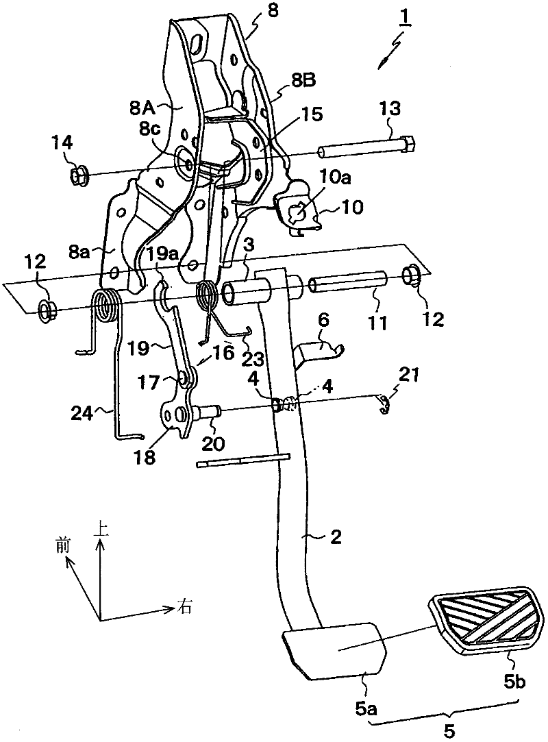
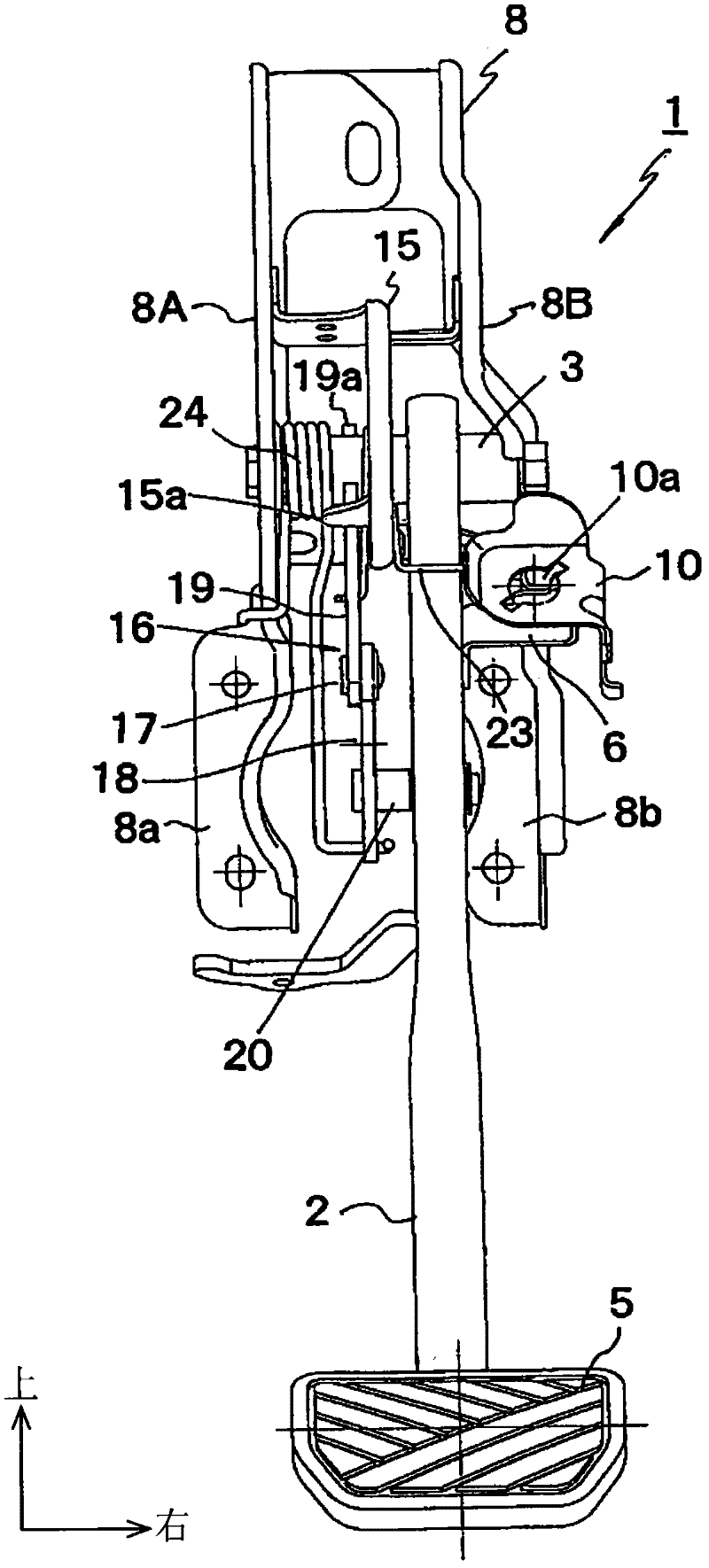
[0032] figure 1 It is an exploded perspective view of the brake pedal device according to the embodiment of the present invention. figure 2 It is a partially cutaway side view showing the state of the brake pedal device at a normal time. image 3 It is a front view showing the state of the brake pedal device at a normal time. Figure 4 It is a partially broken side view showing a state where an impact load is applied to the brake pedal device from the front of the vehicle.

[0033] The brake pedal arrangement 1 shown in the figures comprises a pedal arm 2 . The pedal arm 2 is formed of a pipe. Such as figure 1 As shown, the cylindrical pedal shaft 3 is inserted and fixed to the upper end portion of the pedal arm 2 in the lateral direction, and a circular hole not shown in the lateral direction is penetratingly provided in the middle portion of the pedal arm. ...


PUM


Abstract

In a brake pedal device 1 of a vehicle, including a pedal retreat suppression mechanism for turning a pedal arm 2 to the vehicle front in association with the operation of a dash panel 7 moving to the vehicle rear on receipt of a shock load applied from the vehicle front, the pedal retreat suppression mechanism includes a link mechanism 16 and a trigger 15 attached turnably to a pedal bracket 8 so that a second link 19 of the link mechanism 16 is disengaged from a pedal shaft 3 by the trigger 15 moving to the vehicle rear on receipt of a shock load applied from the vehicle front, an intermediate portion of a first link 18 of the link mechanism 16 is pivotally supported on the pedal arm 2, and a push rod 9a is connected to the lower end portion of the first link 18.

Description

technical field [0001] The present invention relates to a pedal device for a vehicle, which is provided with a pedal retreat suppressing mechanism for interlocking the movement of the dash panel to the rear of the vehicle when an impact load applied from the front of the vehicle is received. Turn toward the front of the vehicle. Background technique [0002] The brake pedal device and the clutch pedal device of the vehicle each have a pedal arm whose upper end is pivotally supported on a pedal bracket coupled to the dash panel. By depressing the pedal of the pedal arm, the driver performs a desired braking or speed change operation by transmitting the displacement of the pedal to a brake master cylinder or a clutch master cylinder. [0003] The master cylinder is mounted directly to the dash. Therefore, there arises a problem that if the dash panel is moved toward the rear of the vehicle by a large impact load applied from the front of the vehicle, the master cylinder moun...

Claims


Application Information

Patent Timeline
Patent Type & Authority Applications(China)
IPC IPC(8): B60T7/06B60K23/02
CPCB60K2023/005B60R21/09B60T7/065G05G1/32Y10T74/20528
Inventor 关友宏
Owner SUZUKI MOTOR CORP
Why Eureka
Try Eureka