High-voltage transmission line maintenance equipment

A technology for high-voltage transmission lines and transmission lines, which is applied to overhead lines/cable equipment, injection devices, etc., and can solve problems such as poor work reliability, inability to drive the drive wheel, and inability to hold down.

Inactive Publication Date: 2017-07-21
HENAN POLYTECHNIC INST
View PDF2 Cites 7 Cited by
  • Summary
  • Abstract
  • Description
  • Claims
  • Application Information

AI Technical Summary

Problems solved by technology

The pressing device (19) of this structure, if the top is too tight, not only the driving wheel (3) will not be able to move but also damage the power line (1), if the top is too loose, the pressing effect will not be achieved at all.
Moreover, only the driving ...

Method used


Image

  • High-voltage transmission line maintenance equipment
  • High-voltage transmission line maintenance equipment
  • High-voltage transmission line maintenance equipment

Examples


Embodiment 1

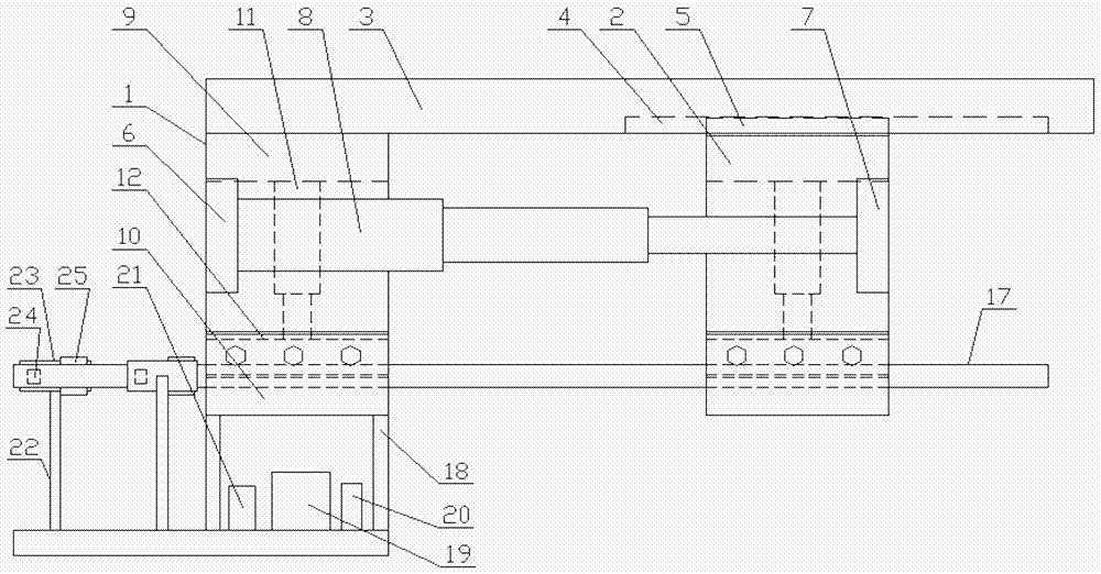
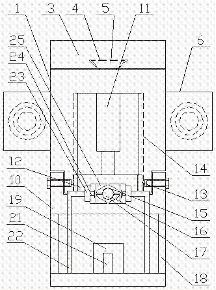
[0037] Such as figure 1 and figure 2 As shown, a high-voltage transmission line maintenance equipment includes a traveling mechanism and a spraying mechanism arranged on the traveling mechanism. The traveling mechanism includes a left traveling support 1 and a right traveling support 2, and a crossbeam is arranged on the upper part of the left traveling support 1 3. A first dovetail groove 4 is provided on the bottom surface of the right side of the beam 3 , and a first dovetail tenon 5 matching the first dovetail groove 4 is arranged on the top of the right traveling support 2 .

[0038] Base 6 is all set on the front and rear sides of described left walking support 1, and push plate 7 is all set on the front and rear sides of described right walking support 2, and the first automatic telescoping link 8 is set on described base 6, and described first automatic The free end of the telescopic rod 8 is arranged on the push plate 7 .

[0039] The structure of the left walking ...

Embodiment 2

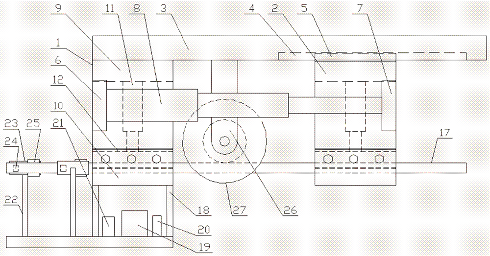
[0050] Such as image 3 and Figure 4 As shown, a high-voltage transmission line maintenance equipment includes a traveling mechanism and a spraying mechanism arranged on the traveling mechanism. The traveling mechanism includes a left traveling support 1 and a right traveling support 2, and a crossbeam is arranged on the upper part of the left traveling support 1 3. A first dovetail groove 4 is provided on the bottom surface of the right side of the beam 3 , and a first dovetail tenon 5 matching the first dovetail groove 4 is arranged on the top of the right traveling support 2 .

[0051] Base 6 is all set on the front and rear sides of described left walking support 1, and push plate 7 is all set on the front and rear sides of described right walking support 2, and the first automatic telescoping link 8 is set on described base 6, and described first automatic The free end of the telescopic rod 8 is arranged on the push plate 7 .

[0052] The structure of the left walking ...

Embodiment 3

[0061] Such as Figure 5 and Figure 6 As shown, the difference between it and Embodiment 2 is that a traction plate 28 is provided on the front and rear sides of the bottom of the spraying bracket 18, and a traction hole 29 is provided on the traction plate 28, and a traction rope 30 is arranged in the traction hole 29.

[0062] An anchor rod or an anchor is arranged at the lower end of the traction rope 30 .

[0063] A position sensor 31 and an alarm 32 are arranged on the lower part of the beam 3 , and both the position sensor 31 and the alarm 32 are electrically connected to the CPU module 21 .

[0064] In this embodiment, traction plates are provided on the front and rear sides of the bottom of the spraying bracket, and traction holes are provided on the traction plates to facilitate fixing the traction rope on the traction plate, so that the ground personnel can prevent the equipment from galloping during the work process through the traction rope. Anchor rods are arra...


PUM


Abstract

The invention discloses a piece of high-voltage transmission line maintenance equipment which comprises a walking mechanism and a spraying mechanism arranged on the walking mechanism. The walking mechanism comprises a left walking bracket and a right walking bracket. A beam is arranged at the upper part of the left walking bracket. A first dovetail groove is arranged in the right bottom of the beam. A first dovetail tenon matching the first dovetail groove is arranged on the top of the right walking bracket. The spraying mechanism for insulation paint spraying is arranged at the bottom of a lower bracket of the left walking mechanism. The spraying mechanism comprises a spraying bracket arranged at the bottom of the lower bracket of the left walking mechanism, an insulation paint can arranged on the spraying bracket, an airless spraying machine arranged on the spraying bracket, and a CPU module. A transmission line can be sprayed with insulation paint in an all-around and even manner. Moreover, the equipment is firmly clamped onto the transmission line in the spraying process. Thus, retreat and fall are avoided in climbing, and the working reliability is improved.

Description

technical field [0001] The invention relates to the technical field of high-voltage transmission line maintenance, in particular to a high-voltage transmission line maintenance equipment. Background technique [0002] The high-voltage transmission lines laid in the early stage generally adopt the form of bare wires to save construction costs, and there are great potential safety hazards. At present, the circuit system is generally constructed by artificially spraying insulating paint to improve the insulation and safety performance of exposed overhead transmission lines. Manual spraying of insulating paint has the disadvantages of low construction efficiency, low construction safety, slow speed and poor consistency of insulation effect. [0003] The invention patent with the patent publication number of CN 102637488 B discloses an overhead bare wire insulation spraying device, which includes an overhead bare wire (1) and a walking hanger (6), and the walking hanger (6) is r...

Claims


Application Information

Patent Timeline
IPC IPC(8): H02G1/02B05B13/04
CPCB05B13/0436H02G1/02
Inventor 马瑛马茵方华丽王风燕田磊杨文铂董珍珍郑冰毕新熙刘婷婷王明绪
Owner HENAN POLYTECHNIC INST
Why Eureka
Try Eureka