Motor having one-body type stator core

A stator iron core, integrated technology, applied in the field of motors, can solve the problems of difficulty in the manufacturing process of the iron core for motors, unoptimized increase in the weight of automobiles, and difficulty in practical application, etc., to simplify the manufacturing process, reduce the loss of the iron core, reduce the The effect of manufacturing costs

Inactive Publication Date: 2014-08-20
AMOTECH
View PDF6 Cites 4 Cited by
  • Summary
  • Abstract
  • Description
  • Claims
  • Application Information

AI Technical Summary

Problems solved by technology

[0015] On the other hand, in the case of a drive motor for an electric vehicle, if a silicon steel plate is used to achieve a high power of 100KW and a high-speed motor of 50,000rpm, as the eddy current (Eddy Current) increases due to high-speed rotation, heat generation will become a problem, and , as it is made into a large size, it cannot be applied to the driving method of the hub motor structure, and it is not preferable in terms of increasing the weight of the car
[0016] Generally, the eddy current loss (Eddy Current Loss) of the amorphous strip is low, but as pointed out in the above-mentioned prior art, the existing motor iron core manufactured by winding or forming and laminating the amorphous strip is due to the manufacturing process Difficult to implement practically
[0017] As described above, in conventional cases, although superior magnetic properties were provided compared with non-oriented electrical steel, block magnetic materials as stators and rotors for electric motors could not be realized due to obstacles that occurred during processing for manufacturing. Use of parts
[0018] And, in the manufacturing method of above-mentioned existing amorphous soft magnetic core, fail to propose the design scheme of the magnetic core that is most suitable for the electric motor field with high power, high speed, high torque, high frequency characteristic

Method used


Image

  • Motor having one-body type stator core
  • Motor having one-body type stator core
  • Motor having one-body type stator core

Examples


Embodiment Construction

[0043] Hereinafter, embodiments of the present invention will be described in detail with reference to the drawings. In this process, the size or shape of the structural elements shown in the drawings will be enlarged to ensure clarity and convenience of description. In addition, terms specifically defined in consideration of the structure and operation of the present invention may vary depending on the user's or operator's intention or custom. These terms should be defined according to the entire content of this specification.

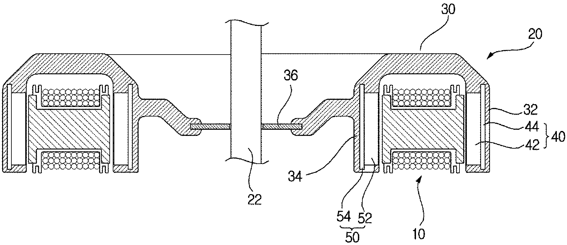
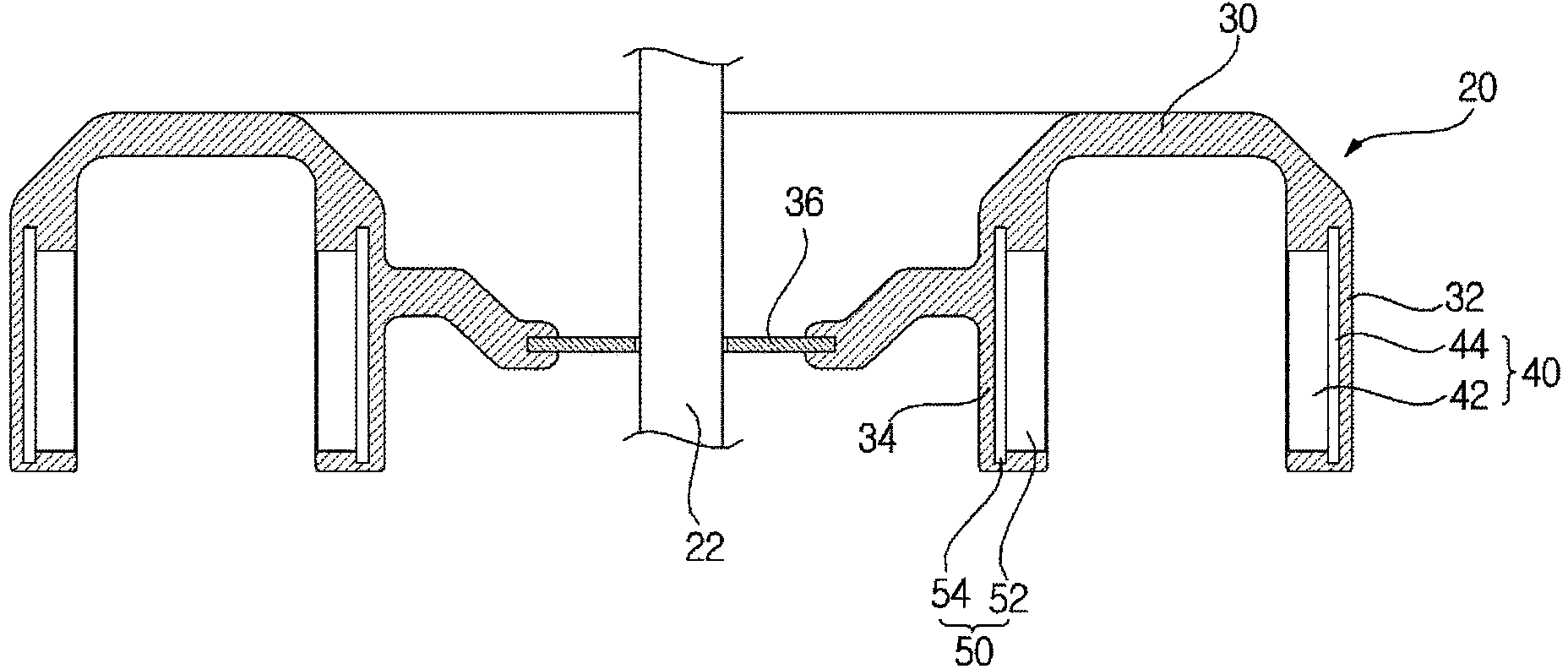
[0044] figure 1 is a sectional view of a motor according to an embodiment of the present invention, figure 2 It is a top view of a motor according to an embodiment of the present invention.

[0045] refer to figure 1 and figure 2 , The motor according to one embodiment includes: a stator 10 ; and a rotor 20 disposed on the outer peripheral surface and the inner peripheral surface of the stator 10 with a predetermined interval, and connected to ...


PUM


Abstract

A motor having an amorphous core according to the present invention comprises: a stator core which is divided in a plural manner and is arranged in an annular shape; a bobbin surrounding an outer peripheral surface of the stator core; a stator which includes a coil wound around an outer peripheral surface of the bobbin; and a rotor which is disposed separately from the stator. The stator core is formed as a single unit, and comprises a yoke around which the coil is wound, and a first flange and a second flange that are disposed at both ends of the yoke. On upper and lower surfaces of the yoke, a coil winding groove is disposed, the height of which is lower than the heights of the upper and lower surfaces of the first flange and the second flange, so that a height of the stator core can be reduced. Thereby, slippage of the motor is allowed.

Description

technical field [0001] The present invention relates to compression molding of a mixture of mixed amorphous metal powder and soft magnetic powder, amorphous metal powder or soft magnetic powder, and integrally molding the stator core, thereby simplifying the manufacturing process and reducing the height of the motor. A slippery motor with a one-piece stator core can thus be realized. Background technique [0002] The slot-type stator is difficult to wind, takes a lot of time to wind the coil, and requires complicated and expensive coil winding equipment. In addition, the structure in which a plurality of gears are formed induces magnetic discontinuity, thereby affecting the efficiency of the motor, and cogging torque is generated depending on the presence or absence of slots. In the case of a material such as an electric steel plate, since the thickness is thick and the iron loss is large, the efficiency in a high-speed motor can only be low. [0003] Various devices used ...

Claims


Application Information

Patent Timeline
Patent Type & Authority Applications(China)
IPC IPC(8): H02K1/18
CPCH02K1/165H02K2213/03H02K1/14H02K21/12H02K1/18
Inventor 金炳秀李世基
Owner AMOTECH
Why Eureka
Try Eureka