Novel blast furnace iron making technology with slag iron discharged from center of furnace bottom

A blast furnace ironmaking and slag discharge technology, which is applied in the direction of discharge devices, can solve problems such as uneven discharge into the furnace, increased air intake resistance at the tuyere, and impossibility of complete overlap of the probe line curves, etc., to achieve safety assurance and prolongation. Effect of blast furnace life

Inactive Publication Date: 2012-03-14
王万元
View PDF7 Cites 4 Cited by
  • Summary
  • Abstract
  • Description
  • Claims
  • Application Information

AI Technical Summary

Problems solved by technology

[0005] (2) Although several iron holes are set on the side wall of the hearth, generally only one iron hole is tapped at a time, and it is impossible for all the taps to tap iron at the same time;
[0010] The difference in air permeability of the circumferential material column due to the uneven treatment of slag and iron will also affect the uniformity of various raw materials entering the blast furnace in actual production
In terms of the upper furnace charge entering the furnace, although the top charge can be very uniform, due to the difference in the gas permeability of the circumferential material column, there is a difference in the speed at which the circumferential charge is smelted and reduced to form slag iron, that is, the descending speed of the circumferential charge is not the same, resulting in furnace The surface of the top material will not be consistent in the circumferential direction, which is manifested on the probe, and the curves of each probe cannot completely overlap
Segregation will occur when the furnace material falls on the material surface. When the situation is serious, there will be abnormalities such as partial material or edge pipeline travel. Therefore, fan-shaped distribution and fixed-point distribution methods need to be retained in the upper distribution method; in the lower air supply, Although the air outlets in the circumferential direction can be kept the same, the air intake volume between the air outlets cannot be exactly the same. The air inlet resistance of the air outlet in the part of the material column with poor air permeability increases (as shown in Table 1), and the air intake volume decreases accordingly. Otherwise, the air permeability is good. The part of the air intake is smooth, and the air intake volume increases accordingly.
For this reason, the air inlet area of ​​the tuyere needs to be adjusted frequently to adapt to or eliminate this unevenness as much as possible; coal injection at the tuyere will also be affected by this, although the pipeline resistance between the distributor and the tuyere can be solved by equal length of the pipeline. However, due to the difference in resistance between the tuyere, the actual amount of coal in each tuyere is difficult to be uniform
[0011] Therefore, the uneven discharge of slag and iron will not only lead to uneven discharge of the circumferential gas flow in the furnace, but also cause uneven discharge of various raw materials into the blast furnace.
The discharge of various products of the blast furnace and the inhomogeneity of various raw materials into the furnace will also cause a series of hazards to the lining of the blast furnace and the cooling equipment of the furnace shaft.
And once the blast furnace is built, this inhomogeneity will accompany the entire furnace and cannot be eliminated. It will affect the reasonable distribution of the two gas flows in the furnace for a long time, that is, it will affect the stability of the blast furnace condition
Therefore, the defect of discharging slag and iron by setting the iron hole on the side wall of the hearth of the blast furnace is the root cause of the uneven distribution of the gas flow in the furnace in the circumferential direction, which in turn leads to the uneven feeding of various raw materials into the blast furnace

Method used


Image

  • Novel blast furnace iron making technology with slag iron discharged from center of furnace bottom
  • Novel blast furnace iron making technology with slag iron discharged from center of furnace bottom
  • Novel blast furnace iron making technology with slag iron discharged from center of furnace bottom

Examples


Embodiment Construction

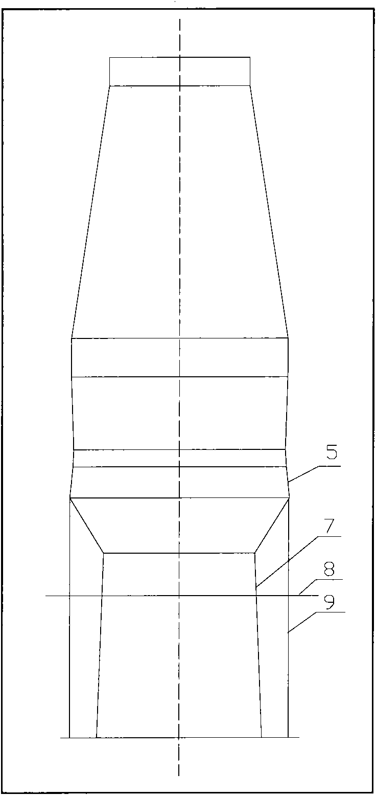
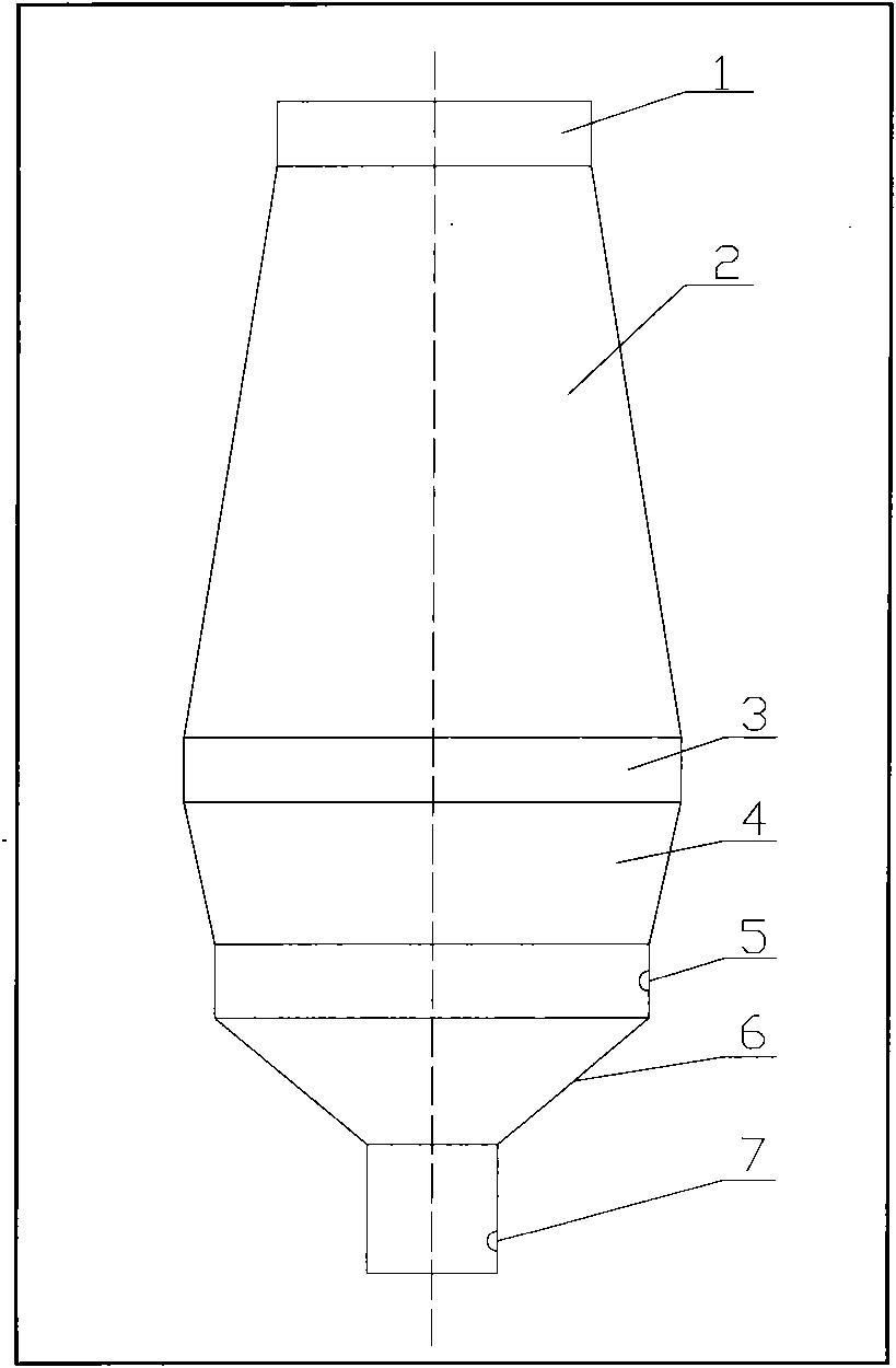
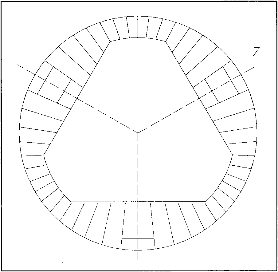
[0027] exist figure 1 and figure 2 The middle furnace throat (1), furnace body (2), furnace waist (3), bosh (4) and tuyere (5) are the same as the current blast furnace structure; the hearth wall (6) below the tuyere (5) faces the The inclination of the center and the inclination angle with the horizontal direction are mainly based on the size of the casthouse space, which meets the needs of the layout of the casting equipment and the treatment of slag and iron in front of the furnace, and avoids the erosion of the furnace lining of the inclined section by hot air. The top of the vertical section of the cylinder is connected; the iron hole (7) is arranged on the side wall of the vertical section, and the casthouse platform (8) is the same as the currently set casthouse platform, and the iron hole (7) and the casthouse platform (8) The elevation is equivalent to that of the current blast furnace, that is, to meet the needs of slag iron treatment in front of the furnace, and a...


PUM


Abstract

The invention relates to a mode of the discharge of blast furnace products molten iron and slag from a blast furnace, and especially relates to a structural form of the hearth of the blast furnace. The molten iron and the slag generated by the blast furnace can be uniformly discharged from the blast furnace, so the nonuniform circumference discharge of a gas flow in the blast furnace can be radically solved, thereby a technical problem that the various raw materials enter the blast furnace in a nonuniform mode because permeabilities of circumferential material columns are different can be eliminated. A technical scheme of the technology is that: an air port and the hearth under the air port are neck-reduced through an inclination segment, and are vertical to the furnace, and an iron port is arranged on the side wall of a vertical segment. The technology is characterized in that: the slag iron generated by the blast furnace uniformly gathers to the hearth along the hot air direction, downward flows through the pressure in the furnace and the gravity, and is discharged to the outside of the furnace through the iron port. So, various raw materials of the blast furnace are kept equal and unified on the circumference in the blast furnace from the charge to the discharge of the furnace, thereby the long term stable production of the blast furnace is easy to realize.

Description

Technical field [0001] This new type of ironmaking process belongs to the improvement of the way in which molten iron and slag, which are products of blast furnace smelting, are discharged out of the furnace. The unevenness of the furnace enables the various raw materials of the blast furnace to be balanced and unified in the circumferential direction of the furnace from the furnace into the furnace to the product out of the furnace, so that the blast furnace condition is easy to maintain long-term stability and smoothness. Background technique [0002] Whether the gas flow distribution at the edge and the center of the blast furnace is reasonable has a great influence on the blast furnace condition, and most of the furnace condition fluctuations are related to this, and it is also the main content of the blast furnace manager's daily adjustment and correction of the furnace condition. The uneven gas flow distribution in the circumferential direction is usually difficult to ...

Claims


Application Information

Patent Timeline
Patent Type & Authority Applications(China)
IPC IPC(8): C21B7/14
Inventor 王万元
Owner 王万元
Why Eureka
Try Eureka