Heating furnace

A heating furnace and furnace body technology, which is applied in the field of heating furnaces, can solve the problems of poor cooling effect of the primary cooling box, poor product uniformity, and low work efficiency, so as to save labor time, improve cooling effect, and reasonable structure Effect

Inactive Publication Date: 2012-03-14
无锡市新科表面工程材料有限公司
View PDF0 Cites 2 Cited by
  • Summary
  • Abstract
  • Description
  • Claims
  • Application Information

AI Technical Summary

Problems solved by technology

[0002] In the traditional technology, during production and processing, the charging boat with products is heated in the inner cavity of the furnace. After heating for a period of time, a push rod is used to manually push the charging boat forward. The heated product enters the cooling box for cooling and heating. In the

Method used


Image

  • Heating furnace

Examples


Example Embodiment

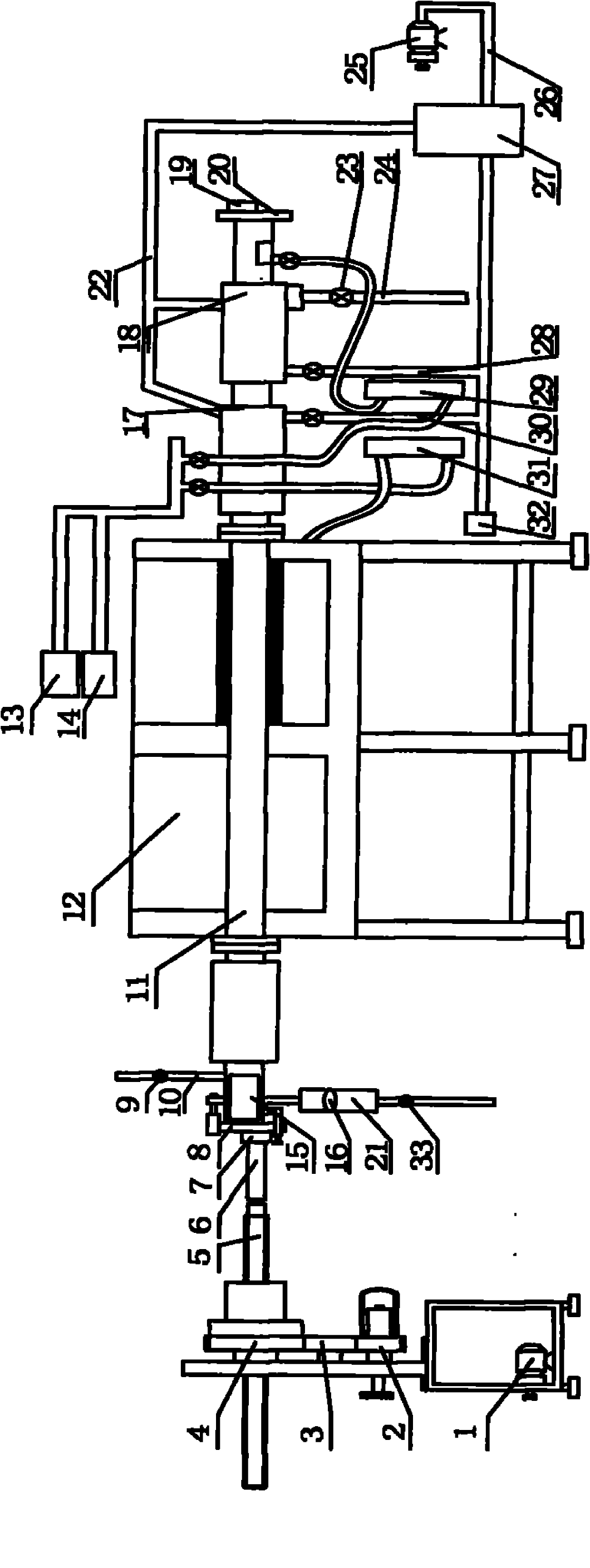
[0014] As shown in Figure 1, a heating furnace of the present invention includes a charging boat 15 placed in the furnace cavity 11, a furnace body 12, a propulsion device, a sewage mechanism, a grading cooling device, a dual-channel air supply device, and a feed The front end of the furnace body 12 is provided with a feed door 8 and the end is provided with a discharge door 20. The propulsion device includes a clutch device, a threaded push rod 5 and a push rod 6, and the clutch device It includes a gear a2, a gear b3, a gear c4 and a motor 1. The staged cooling device includes a primary cooling box 17 and a secondary cooling box 18. The dual air supply equipment includes an air supply source 13, a backup air supply source 14, A gas flow meter 29 and a backup gas flow meter 31. The motor 1 is connected to the gear a2, the gear b3 is connected to the gear a2, the gear c4 is connected to the gear b3, and the gear c4 is connected to a threaded push rod through internal tooth patte...


PUM


Abstract

The invention relates to a heating furnace, which comprises a loading ship, a furnace body, a propulsion unit, a sewage disposal mechanism, a grading cooling device, double-path air supply equipment, a feeding door and a discharging door, wherein all components are arranged in a furnace body cavity; the front end of the furnace body is provided with the feeding door; the tail end of the furnace body is provided with the discharging door; the propulsion unit comprises a clutch device, a threaded push rod and a push rod; the grading cooling device comprises a first-level cooling box and a second-level cooling box; the double-path air supply equipment comprises a power supply source, a spare power supply source, a gas flowmeter and a spare gas flowmeter; the clutch device is connected with the threaded push rod; the push rod is connected with the threaded push rod; the axis centers of the push rod and the threaded push rod are on the same horizontal line; the push rod is connected with the loading ship arranged in the furnace body cavity; the upper part of the feeding door is provided with an exhaust pipe; the lower part of the feeding door is provided with a sewage disposal mechanism; and the position close to the discharging door on the tail end of the furnace body, is successively provided with the first-level cooling box and the second-level cooling box. According to the heating furnace, manual work time is saved, product quality is improved, and energy is saved.

Description

technical field [0001] The invention relates to a heating furnace. Background technique [0002] In the traditional technology, during production and processing, the charging boat with products is heated in the inner cavity of the furnace. After heating for a period of time, a push rod is used to manually push the charging boat forward. The heated product enters the cooling box for cooling and heating. In the project, the feed door of the furnace body is open, and at the same time, there is a gas supply source to provide gas protection for the furnace cavity, which is too wasteful of energy, the work efficiency is not high, and the uniformity of the product is not good. The cooling effect of the primary cooling box Not good. Contents of the invention [0003] The purpose of the present invention is to provide a heating furnace, in order to save the energy of the heating furnace and achieve a better cooling effect. [0004] The technical scheme adopted in the present inve...

Claims


Application Information

Patent Timeline
IPC IPC(8): F27B9/18F27B9/30
Inventor 薛永宗薛鉴王玉琦
Owner 无锡市新科表面工程材料有限公司
Why Eureka
Try Eureka