Movable adjusting drive unit for optical elements

A technology of driving device and optical element, which is applied in the direction of optical element, optics, exposure device of photographic plate making process, etc. It can solve the problems of difficult processing, complex structure of adjusting lens mechanism, small stroke, etc., and achieve good repeatability and stability, reduce Difficult design and easy maintenance

Active Publication Date: 2012-03-14
SHANGHAI MICRO ELECTRONICS EQUIP (GRP) CO LTD
View PDF5 Cites 0 Cited by
  • Summary
  • Abstract
  • Description
  • Claims
  • Application Information

AI Technical Summary

Problems solved by technology

[0004] The present invention aims to solve the technical problems in the prior art, such as the complex structure of the lens adjustment mechanism in the exposure equipment, the small stroke, and the difficulty in processing.

Method used


Image

  • Movable adjusting drive unit for optical elements
  • Movable adjusting drive unit for optical elements
  • Movable adjusting drive unit for optical elements

Examples


Embodiment Construction

[0019] In order to make the technical features of the present invention more comprehensible, specific embodiments are given below in conjunction with the accompanying drawings to further describe the present invention.

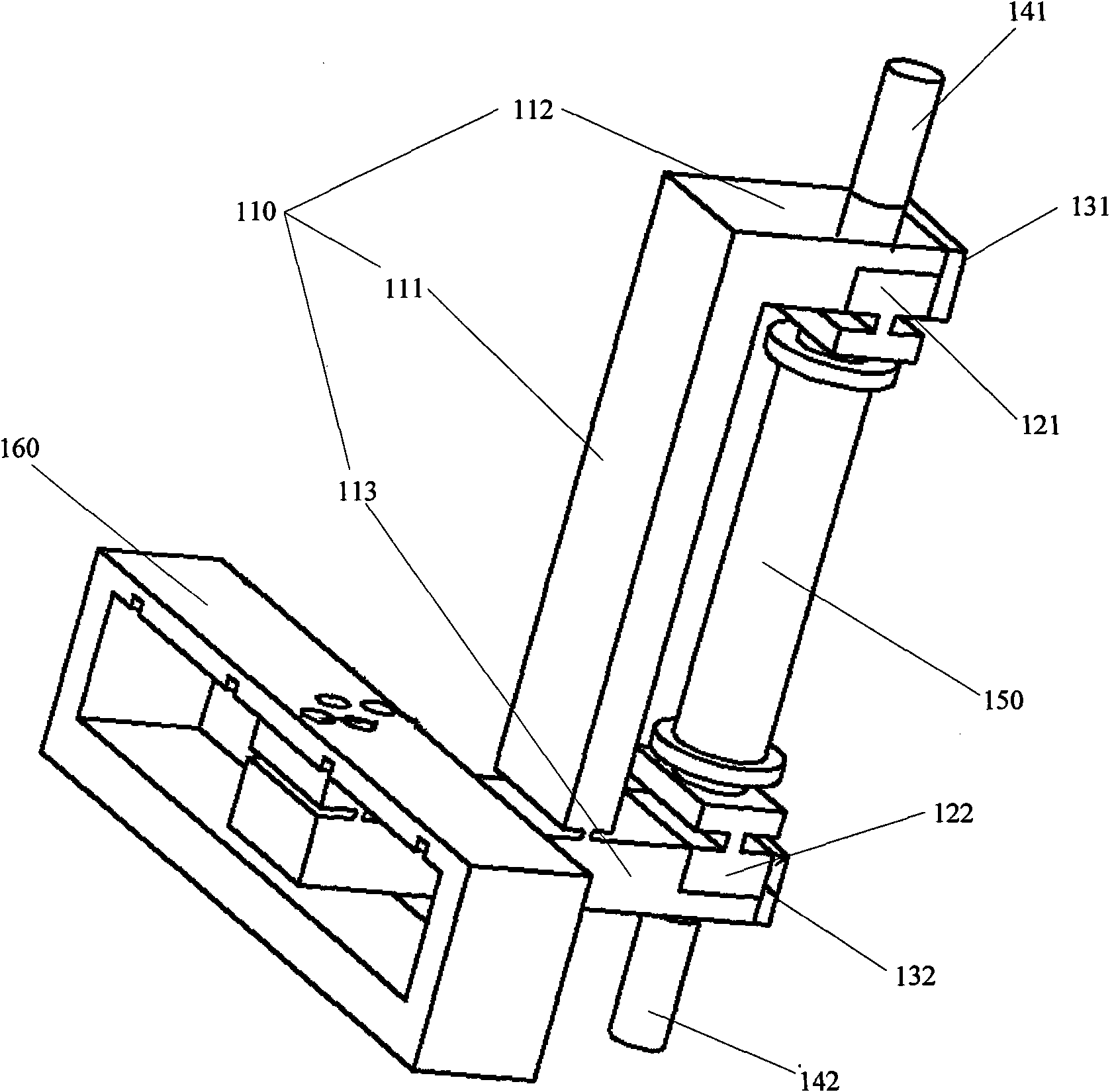
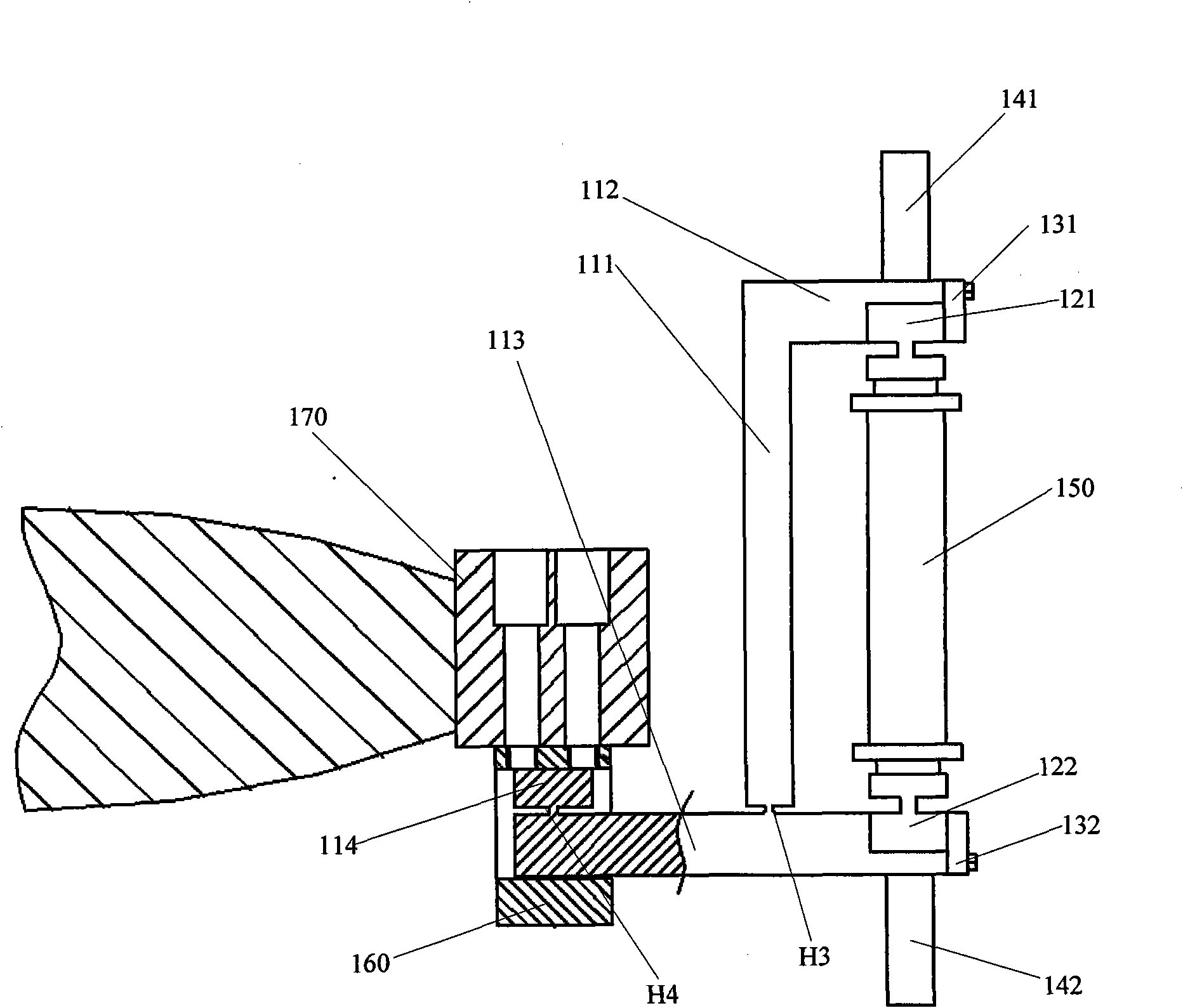
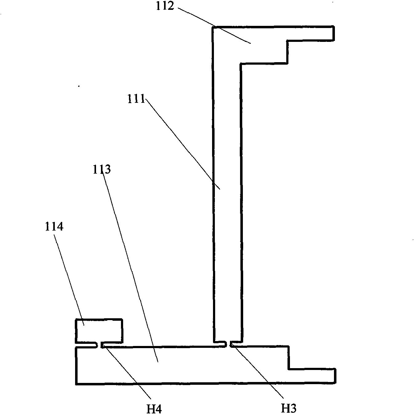
[0020] Please refer to Figure 1A and 1B , which is a schematic structural diagram of a movable optical element adjustment driving device provided by an embodiment of the present invention. The movable optical element adjustment driving device includes: a main trunk 110; first and second flexible mounts 121, 122 respectively arranged at two ends of the main trunk 110; the first and second flexible mounts are fixed Blocks 131, 132 are fixed on the sides of the two ends of the main trunk to limit the movement of the first and second flexible mounts 121, 122 up and down; the first and second adjustment screws 141, 142 respectively pass through the main trunk 110 The threaded holes on the top are connected to the first and second flexible mounts 121, 122;

[002...


PUM


Abstract

The invention provides a movable adjusting drive unit for optical elements, comprising: a main body; a first flexible soleplate and a second flexible soleplate which are respectively arranged at the two ends of the main body; a first flexible soleplate fixed block and a second flexible soleplate fixed block which are fixed on the sides of the two ends of the main body to limit the first flexible soleplate and the second flexible soleplate to move up and down; a first adjusting screw and a second screw which are respectively connected with the first and second flexible soleplate through the screwed holes on the main body; a driving mechanism which is fixed between the first flexible soleplate and the second flexible soleplate; and a deformation block which is connected with one end of the main body. The invention has the advantages of low hysteresis quality, strong load capacity, good repeatability and stability, high precision (which can reach to a nanometer level ), convenient maintenance and the like, and has the advantages of large distance of travel, simple structure, low processing difficulty and the like.

Description

technical field [0001] The invention relates to the technical field of semiconductor manufacturing, and in particular to a movable optical element adjustment driving device applied in exposure equipment. Background technique [0002] With the continuous development of semiconductor technology, the manufacturing process of semiconductor devices has higher and higher requirements for precision. For example, in the lithography process, the projection optical system in the exposure equipment of advanced lithography machine needs smaller and smaller wave phase difference and distortion. , and at the same time, in the exposure equipment of this projection optical system, the changes of phase difference and distortion caused by various environments and other factors can be easily compensated in real time. In order to solve this type of problem, it is generally compensated by setting one or several lenses whose position or shape can be adjusted. [0003] In the prior art, there are...

Claims


Application Information

Patent Timeline
Patent Type & Authority Applications(China)
IPC IPC(8): G03F7/20G02B7/02
Inventor 陈明杰王洪尊
Owner SHANGHAI MICRO ELECTRONICS EQUIP (GRP) CO LTD
Why Eureka
Try Eureka