Roller rotary offset printing press having at least one coating unit with a chamber blade and an anilox roller

A web and printing machine technology, applied in the field of web pivoting lithographic printing machines, can solve the problems of high equipment consumption and achieve the effects of reducing costs, less space, and preventing ink or paint from blurring

Inactive Publication Date: 2012-03-14
KOENIG & BAUER AG
View PDF12 Cites 2 Cited by
  • Summary
  • Abstract
  • Description
  • Claims
  • Application Information

AI Technical Summary

Problems solved by technology

The use of such coatings requires a relatively high expenditure on equipment

Method used


Image

  • Roller rotary offset printing press having at least one coating unit with a chamber blade and an anilox roller
  • Roller rotary offset printing press having at least one coating unit with a chamber blade and an anilox roller
  • Roller rotary offset printing press having at least one coating unit with a chamber blade and an anilox roller

Examples


Embodiment 1

[0045] Example 1: "Directly, in a winding manner"

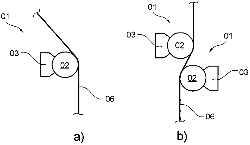
[0046] This example is also figure 1Visible in a). The printing substrate 06 is in direct contact with the anilox roller 02 during the printing process. The paint is transferred directly onto the printing material 06 from the depressions in the outer surface of the anilox roller 02 . The paint dots delivered by the individual depressions are more easily movable and connected to one another after their delivery, so that a continuous paint surface is achieved at the desired position on the printing material 06 . An anilox roll 02 with a relatively fine mesh is used for this, which means that in the case of linear structures the thread density is preferably between 90 and 130 threads per centimeter. The printing material 06 is wound and pressed onto the anilox roller 02, that is, the printing material 06 not only touches the anilox roller 02 on a straight line parallel to the rotation axis of the anilox roller 02, but also th...

Embodiment 2

[0048] Example 2: "Directly, by embossing"

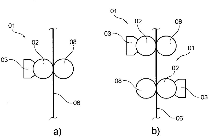
[0049] This example is also figure 2 Visible in a). The printing material 06 is coated directly by the anilox roller 02 as in Example 1. The anilox roller 02 is designed as in Example 1 and the transfer of the coating is also carried out exactly as in Example 1, where the transferred coating spots also move to desired positions on the printing material 06 to form a through coating surface. The embossing roller 08 presses the printing material 06 against the anilox roller 02 in order to achieve a better contact between the anilox roller 02 and the printing material 06 and thus improve the exit of the paint from the recessed part of the anilox roller 02 to the printing material Pass on 06. The printing material 06 can be wound around the anilox roller 02 and / or the embossing roller 08 or can also be guided in a straight line between the anilox roller 02 and the embossing roller 08 , ie the contact area between the printing materia...

Embodiment 3

[0051] Example 3: "With applicator roll, in a winding manner"

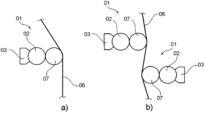
[0052] This example is also image 3 Visible in a). The anilox roller 02 is in contact with the applicator roller 07 in addition to the chambered doctor blade 03 . The applicator roller 07 is again in rolling contact with the printing material 06 . Since the printing material 06 is not in direct contact with the anilox roller 02 , the linear density of the recesses in the outer surface of the anilox roller 02 preferably lies in the range of 40 to 80 threads per centimeter. The printing material 06 wraps around the applicator roller 07, so that the contact between the applicator roller 07 and the printing material 06 is not designed as a line but as a plane, and a compression between the printing material 06 and the applicator roller 07 takes place force. From within the chambered doctor blade 3 , the paint is transferred via the anilox roller 02 to the applicator roller 07 and from there onto the printing mate...


PUM


Abstract

The invention relates to a roller rotary offset printing press having at least one coating unit (01) and at least one printing unit (11), wherein the coating unit comprises at least one chamber blade (03) comprising a water-based coating and at least one anilox roller (02), wherein the coating unit is arranged along a transport path of a print stock downstream of the at least one printing unit of the roller rotary offset printing press and wherein at least one pair of two rollers is arranged that together form a coating gap and wherein at least one roller of said at least one pair is in contact with the at least one anilox roller and wherein the conveyed volume at least on one part of the shell surface of the at least one anilox roller is filled by an amount of coating, the mass of which based on this part of the shell surface of the at least one anilox roller, minus a water portion, equals on average a maximum of 4 g / m2. A blanket having several layers can be placed or is placed on at least one roller of the coating unit.

Description

technical field [0001] The invention relates to a web pivot offset printing press according to the preamble of claim 1 or the preamble of claim 2 with at least one coating unit and at least one printing unit. Background technique [0002] A method of covering a print with a paint layer is disclosed in the manufacture of a print. This achieves a protective effect on the one hand, since the ink previously applied to the printing material is fixed and fading, for example, on parts of the printing press, on another printed product or on the hands of the person holding the printed product is prevented. or the ink is blurred. On the other hand, higher-quality prints are obtained because of the different effects achieved with a large number of different paints. For example, glossy or matte paints can be used which completely or partially cover the print. Fragrance paints are also known, which release fragrances stored in small capsules with slight rubbing, or paints with metalli...

Claims


Application Information

Patent Timeline
Patent Type & Authority Applications(China)
IPC IPC(8): B41F23/08B41F31/02
CPCB41F23/08B41F31/027
Inventor 伯恩特·库特·马祖赫沃尔夫冈·奥托·雷德尔
Owner KOENIG & BAUER AG
Why Eureka
Try Eureka