Optical multiplexing terminating device, passive optical network system, and method for allocating frequency

A passive optical network system and optical multiplexing technology, applied in optical multiplexing systems, multiplexing system selection devices, wavelength division multiplexing systems, etc., can solve interference, optical signal conflicts, etc. question

Inactive Publication Date: 2012-03-14
HITACHI LTD
View PDF7 Cites 7 Cited by
  • Summary
  • Abstract
  • Description
  • Claims
  • Application Information

AI Technical Summary

Problems solved by technology

That is, since the length (transmission distance) of the combined trunk fiber and branch fiber from the OLT to each ONU is inconsistent, the transmission delay (delay amount) between each ONU and OLT is inconsistent, even if each ONU sends signals at different timings , there is also the possibility that the optical signals output from each ONU may conflict and interfere with each other on the backbone optical fiber

Method used


Image

  • Optical multiplexing terminating device, passive optical network system, and method for allocating frequency
  • Optical multiplexing terminating device, passive optical network system, and method for allocating frequency
  • Optical multiplexing terminating device, passive optical network system, and method for allocating frequency

Examples


Embodiment Construction

[0096] Hereinafter, the configuration and operation of the PON according to the present embodiment and the wavelength allocation method for realizing the present scheme will be described in detail using the drawings.

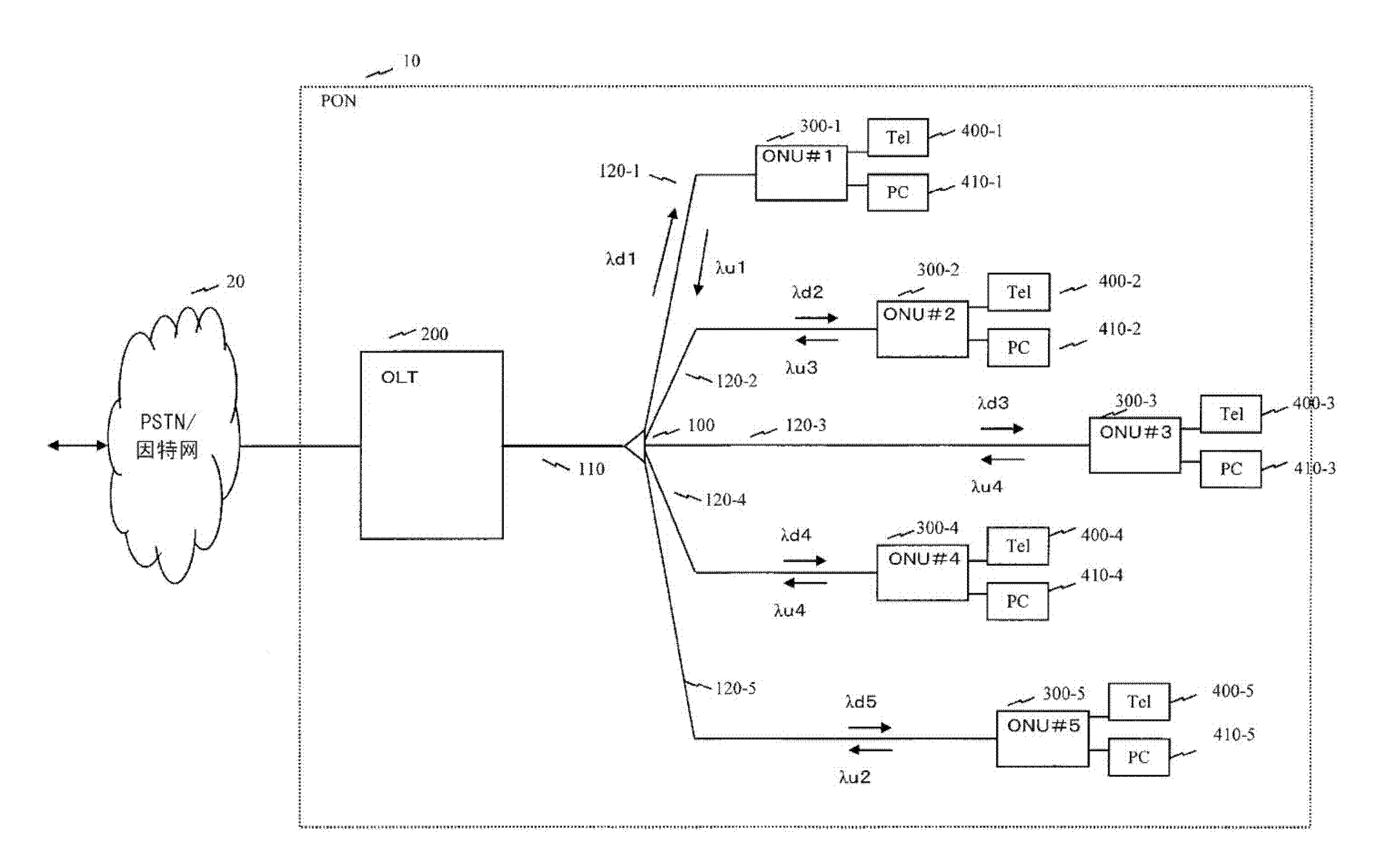
[0097] 1. Passive optical network system

[0098] In the following description, assume a PON configured to process wavelength division multiplexed data after allocating wavelengths to each of five ONUs connected to the OLT. One of the ONUs statically allocates unique wavelengths (λd1, λd2, ..., λd5). In addition, among the wavelengths allocated for upstream data from the ONU to the OLT, dynamically allocates 100Mbit / s (accurately 103.68Mbit / s) s, the time slot length is 1620 bytes), 500Mbit / s (accurately 518.4Mbit / s, the time slot length is 8100 bytes), 1Gbit / s (accurately 1036.8Mbit / s, the time slot length is 16200 bytes), 10Gbit / s (accurately 10368Mbit / s, the slot length is 162000 bytes) corresponding to the data wavelengths (λu1, λu2, λu3, λu4), using the ab...


PUM


Abstract

A passive optical network system such that the power consumption can be reduced as much as possible according to the end-user traffic. An OLT uses the DBA function thereof and sequentially uses frequencies in ascending order of transmission rate in order to sequentially allocate bands to ONUs in ascending order of the requested bandwidth. At this time, a frequency to be allocated is selected so that the bandwidth allocated to each ONU is narrower than a maximum bandwidth through which transmission using the allocated wavelength is enabled. An OLT, by using the DBA function, uses a grant area to specify the transmission timing of the secondary station and to inform the specified transmission timing to the secondary station. In addition to the area where grant information is stored, an area is set for storing information used to inform the secondary station of a new frequency to be used. Each ONU carries out uplink communication using the specified frequency at a transmission rate determined by the frequency.

Description

technical field [0001] The present invention relates to an optical multiplexing terminal device, a passive optical network system, and a wavelength distribution method, in particular to an optical multiplexing method in a passive optical network system in which optical network terminal devices such as multiple subscriber connection devices share an optical transmission line. A multiplexing terminal device, a passive optical network system, and a wavelength allocation method. Background technique [0002] In order to send and receive large-capacity image signals or data through the communication network, in the access network that connects the subscribers to the communication network, the high-speed and wide-band communication network is continuously improved, and the introduction of the International Telecommunication Union (hereinafter referred to as ITU -T) The passive optical network system (Passive Optical Network system, hereinafter referred to as PON) stipulated in G.9...

Claims


Application Information

Patent Timeline
Patent Type & Authority Applications(China)
IPC IPC(8): H04L12/44H04B10/20H04B10/24H04J14/00H04J14/02H04B10/27H04B10/272
CPCH04J14/0282H04J14/0246H04J14/0252H04Q2213/1301
Inventor 坂本宪弘加沢徹矢岛祐辅土屋明彦
Owner HITACHI LTD
Why Eureka
Try Eureka