
Electric control breast pump

An electric control, breast pump technology, applied in breast pump and other directions, can solve problems such as mixing into milk, influence, easy damage to the orifice, etc.

Inactive Publication Date: 2012-03-21
温晓兰
View PDF6 Cites 16 Cited by
  • Summary
  • Abstract
  • Description
  • Claims
  • Application Information

AI Technical Summary

Problems solved by technology

[0005] In order to overcome the inconvenient operation, poor uniformity and stability of breast pumping, the orifice in the middle of the diaphragm is easily damaged and the durability of the diaphragm is affected, and the air will enter the small valve chamber through the gap of the orifice in the existing manual control breast pump. , and mixed into the milk to affect its quality, and the air that is close to the negative pressure cycle of the electric control breast pump is not isolated from the sucked milk. There are too many bubbles in the sucked milk, and the baby is easy to vomit after drinking, and the air is mixed into the milk. It will affect its quality and other defects, the present invention provides an improved electric control breast pump, which can overcome the defects of the prior art

Method used


Image

  • Electric control breast pump
  • Electric control breast pump
  • Electric control breast pump

Examples


Embodiment Construction

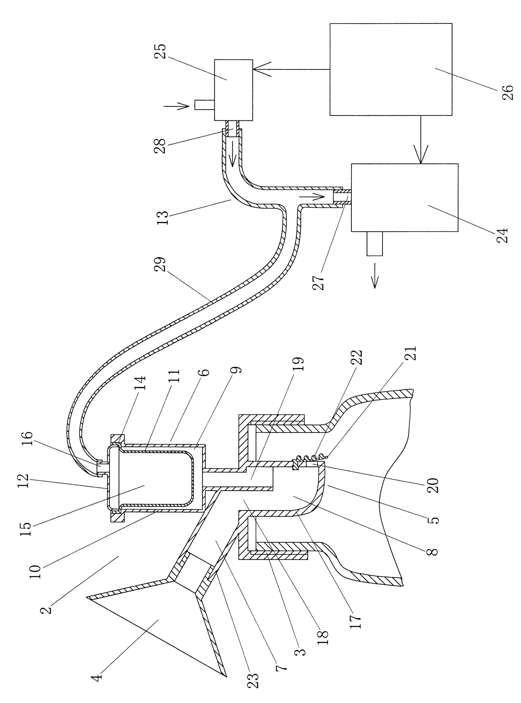
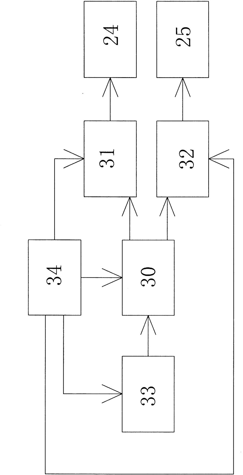
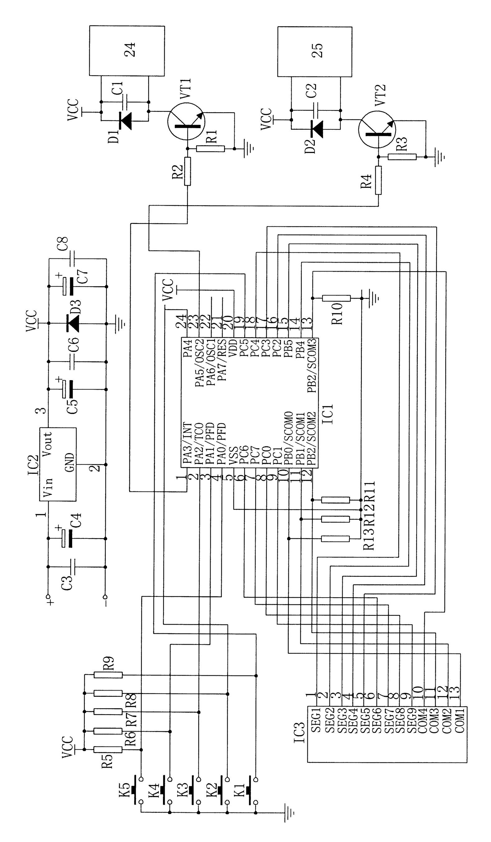
[0024] refer to figure 1 , the electric control breast pump includes a feeding bottle 1 and a breast pump main body 2, and the feeding bottle 1 and the breast pump main body 2 are connected together by threads 3, wherein the breast pump main body 2 includes a bottle cap seat 3 and a breast pumping part 4 , connect the milk valve 5 and the negative pressure generating part 6, the bottle cap seat 3 is connected to the bottle mouth of the feeding bottle 1 through the thread 3, the milk sucking part 4 and the negative pressure generating part 6 are arranged on the top of the bottle cap seat 3, and the milk connecting valve 5 is arranged on the At the bottom of the bottle cap seat 3, the sucking part 4 communicates with the valve chamber 8 of the milk valve 5 through the milk passage 7, and the negative pressure chamber 9 of the negative pressure generating part 6 communicates with the valve chamber 8 of the milk valve 5. It is characterized in that : the negative pressure generati...


PUM


Abstract

The invention relates to an electric control breast pump, which aims to solve the disadvantages that a proximate manual or electric breast pump is inconvenient to operate, the uniformity and the stability for milk pumping are bad, a membrane is not durable, air can enter the milk to cause excessive bubbles in the milk, and the quality of the milk is influenced. The key points of the technical scheme are as follows: the electric control breast pump comprises a milk bottle and a breast pump main body, wherein, the breast pump main body comprises a bottle cover seat, a milk pumping part, a milk receiving valve and a negative pressure generating part; the milk pumping part and the negative pressure generating part are arranged at the top of the bottle cover seat; the milk receiving valve is arranged at the bottom of the bottle cover seat; the milk pumping part and a negative pressure cavity of the negative pressure generating part are communicated with a valve cavity of the milk receiving valve; in addition, the electric control breast pump is characterized in that the negative pressure generating part comprises a negative pressure cavity seat, a soft bowl-shaped membrane, a cavity seat cap and an electric air suction device, the bowl-shaped membrane is positioned in the negative pressure cavity of the negative pressure cavity seat and is arranged on a negative pressure cavity opening through a bowl opening, the cavity seat cap is tightly connected with the negative pressure cavity opening of the negative pressure cavity seat and can mutually compress the bowl opening of the bowl-shaped membrane and the negative pressure cavity opening, and an inner concave air cavity of the bowl-shaped membrane is communicated with the electric air suction device through an air hole formed on the cavity seat cap.

Description

technical field [0001] The invention relates to a breast pump used for expressing breast milk accumulated in the mammary gland during breastfeeding, in particular to an electrically controlled breast pump. Background technique [0002] Women who are breastfeeding often have problems such as newborn babies who do not have the strength to suck milk, too much milk that cannot be stored and wasted, mammary gland inflammation that affects milk discharge, nipple injury or inverted nipples that cannot be fed, so there are problems that can help Breast pumps for women who are breastfeeding overcome these problems. [0003] Most of the breast pumps currently in use are manually controlled to suck milk. Closer is a breast pump disclosed in Chinese Patent No. 200920059187.7, which has a buffer, a small valve chamber connected to the main body of the breast pump, a connector, a feeding bottle, a diaphragm, a handle, and a protective cover, wherein the main body of the breast pump The ...

Claims


Application Information

Patent Timeline
IPC IPC(8): A61M1/06
Inventor 温晓兰
Owner 温晓兰
Learn More