

Milling cutter for ultrahigh-voltage conductor
An ultra-high voltage and conductor technology, which is applied in the direction of milling cutters, milling machine equipment, milling machine equipment details, etc., can solve problems such as knife jamming and sticking knives
Inactive Publication Date: 2012-03-21
JIANGSU YONGLONG ELECTRIC
View PDF0 Cites 0 Cited by
- Summary
- Abstract
- Description
- Claims
- Application Information
AI Technical Summary
Problems solved by technology
However, when using ordinary milling cutters for processing, it is found that there will be "cracking" and "jamming". Even if a large amount of lubricating coolant is used, it is difficult to avoid this phenomenon.
Method used
View moreImage
Smart ImageViewing Examples

Examples
Embodiment Construction
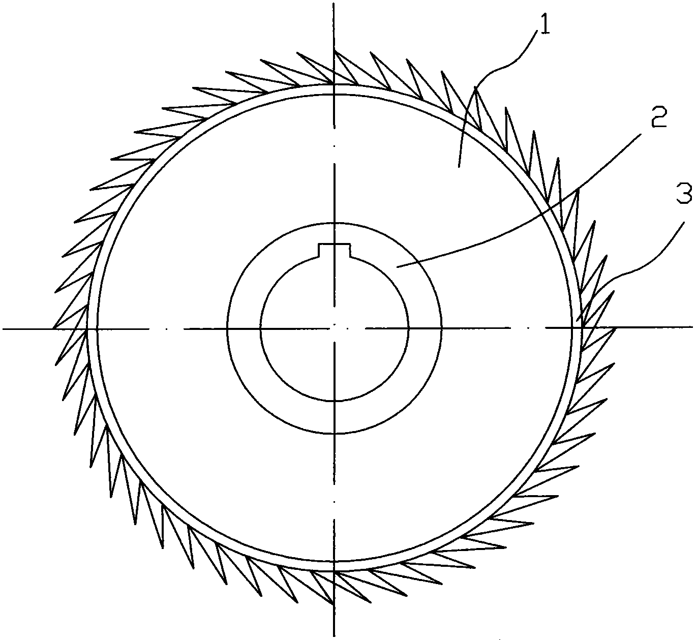
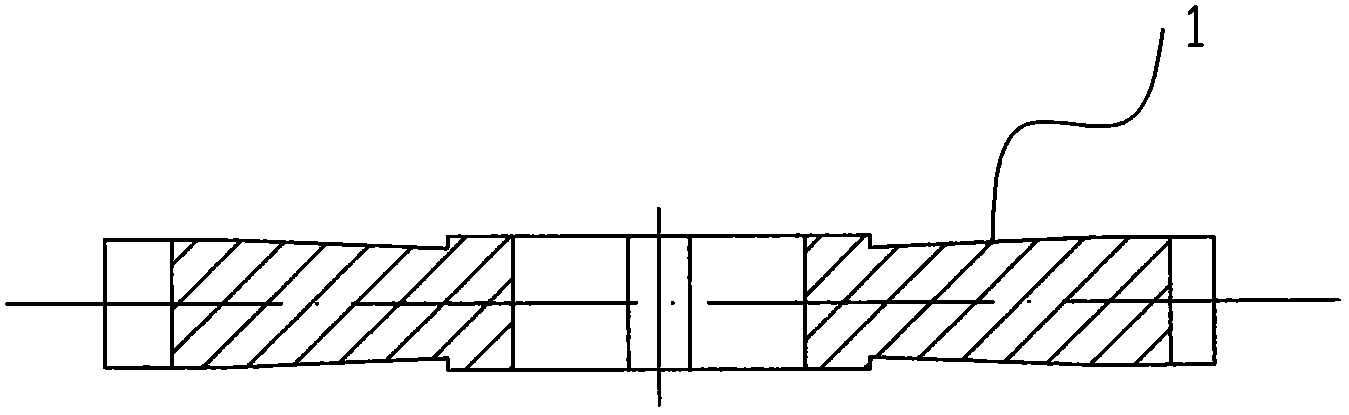
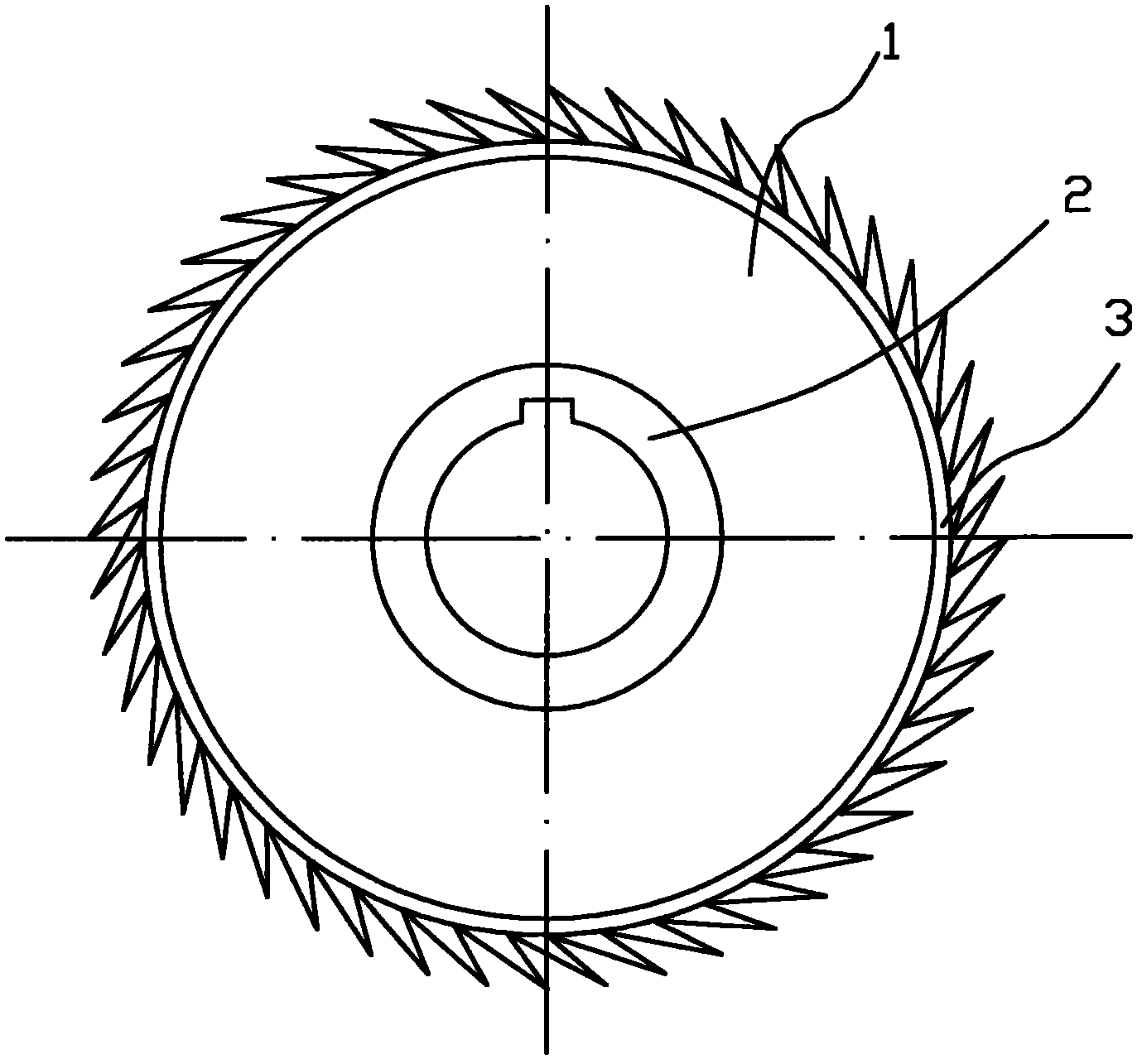
[0009] The present invention as figure 1 , 2 As shown, the milling cutter is in the shape of a disk as a whole, and the two ends of the disk 1 are tapered, so that the 3 parts of the cutter teeth are thicker than the 2 parts of the cutter hole.
Login to View More PUM
 Abstract
The invention discloses a milling cutter for an ultrahigh-voltage conductor, relating to the improvement on a special milling cutter structure for machining a conductor in an ultrahigh-voltage power grid. By improving the milling cutter structure, the phenomena of cutter obstruction and cutter clamping are avoided. The milling cutter is of a disc shape, two end surfaces of the disc-shaped milling cutter are conical surfaces, and a cutter tooth part is thicker than a cutter hole part. According to the invention, the structure of a common milling cutter of which the two end surfaces are planes is changed, and the two end surfaces of the milling cutter are changed into the conical surfaces specific to the characteristic that an aluminum material has a high thermal deformation coefficient. Accordingly, when the cutter is fed, the phenomena of the cutter obstruction and the cutter clamping caused by that a machined surface extrudes the end surfaces of the milling cutter can be prevented. Because the milling cutter bears a small load when the aluminum material is machined, the service life of the milling cutter cannot be shortened due to the structure, and the requirements for machining the aluminum material are completely met.
Description
technical field [0001] The invention relates to the improvement of the structure of a special milling cutter for conductor processing in an extra-high voltage power grid. Background technique [0002] The transmission voltage of the UHV power grid is high, and the cross-sectional area of the transmission conductor is required to be as large as possible. At present, copper materials are generally used to make conductors, but due to the scarcity of copper resources, the cost is high and the weight is heavy, and the support body requires high strength. The applicant proposes to use aluminum material to make conductors instead of copper material. However, in the test, we found that due to the extremely high carrying voltage, the aluminum material is very easy to generate heat, resulting in an increase in the conductor resistance. It is necessary to mill out several grooves at the end of the conductor to increase the surface area of the end to facilitate heat dissipation. ...
Claims
Login to View More Application Information
Patent Timeline
 Patent Type & AuthorityApplications(China)
IPC IPC(8): B23C5/02B23C3/28
Inventor张道勇
OwnerJIANGSU YONGLONG ELECTRIC