Installing and fixing structure of suspension torsion bar of torsion beam of automobile

A technology of fixed structure and torsion beam, applied in the direction of suspension, elastic suspension, vehicle parts, etc., can solve problems such as strength not meeting design requirements, poor welding performance, welding cracking, etc., to improve stress concentration and connection strength. , the effect of reducing the strength requirements

Inactive Publication Date: 2012-03-21
CHONGQING CHANGAN AUTOMOBILE CO LTD
View PDF5 Cites 4 Cited by
  • Summary
  • Abstract
  • Description
  • Claims
  • Application Information

AI Technical Summary

Problems solved by technology

Since the material of the torsion bar is high-carbon steel and the material of the trailing arm is low-carbon steel, the welding performance is poor, and the strength does not meet the design requirements, which is prone to welding cracking problems

Method used


Image

  • Installing and fixing structure of suspension torsion bar of torsion beam of automobile
  • Installing and fixing structure of suspension torsion bar of torsion beam of automobile
  • Installing and fixing structure of suspension torsion bar of torsion beam of automobile

Examples


Embodiment 1

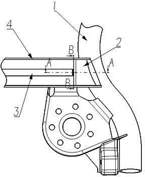
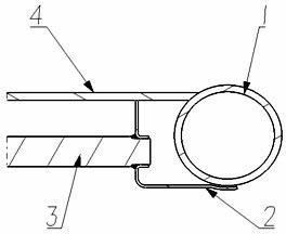
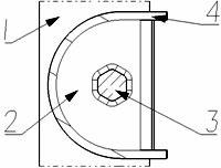
[0013] Embodiment one: see figure 1 , figure 2 and image 3 The shown installation and fixing structure of a torsion beam suspension torsion bar for an automobile includes an intermediate bracket 2 and a torsion bar 3; Connect, the top of the right end of the horizontal part of the intermediate bracket is fixedly connected with one side of the longitudinal arm 1, and the right end of the torsion beam 4 is fixedly connected with the other side of the longitudinal arm 1; There are hexagonal flanging holes, and the right end of the torsion bar is correspondingly a hexagonal structure, and the hexagonal structure is in interference fit with the hexagonal flanging holes in the middle of the vertical part of the middle bracket, and is fixedly connected by welding .

Embodiment 2

[0014] Embodiment two: see figure 1 , figure 2 and image 3 The shown installation and fixing structure of a torsion beam suspension torsion bar for an automobile includes an intermediate bracket 2 and a torsion bar 3; Connect, the top of the right end of the horizontal part of the intermediate bracket is fixedly connected with one side of the longitudinal arm 1, and the right end of the torsion beam 4 is fixedly connected with the other side of the longitudinal arm 1; There is a quadrilateral flanging hole, and the right end of the torsion bar is a quadrilateral structure correspondingly, and the quadrilateral structure is in interference fit with the quadrilateral flanging hole on the middle part of the vertical part of the intermediate bracket, and is fixedly connected by welding.

[0015] The torsion bar and the intermediate bracket are assembled with interference, and then strengthened by carbon dioxide shielded welding. The intermediate bracket is fixedly connected wi...


PUM


Abstract

The invention discloses an installing and fixing structure of a suspension torsion bar of a torsion beam of an automobile, comprising a middle bracket and the torsion bar. The installing and fixing structure is characterized in that the section of the middle bracket is L-shaped; the upper end of the vertical part of the middle bracket is fixedly connected with a torsion cross beam; the upper surface of the right end of the horizontal part of the middle bracket is fixedly connected with one side of a longitudinal arm; the right end of the torsion cross beam is fixedly connected with the other side of the longitudinal arm; the middle part of the vertical part of the middle bracket is provided with a polygonal flanging hole; the right end part of the torsion bar is of a polygonal structure correspondingly; and the polygonal structure is in interference fit with the polygonal flanging hole on the middle part of the vertical part of the middle bracket, and the polygonal structure and the polygonal flanging hole are fixedly connected by welding. In the installing and fixing structure, the connecting strength between the torsion bar and the longitudinal arm is improved, the strength requirement for welding seams is reduced, so that the whole connecting strength is well improved and the service life of the whole part is prolonged; and the problems of low strength and cracking of the welding seams for adopting direct welding between the torsion bar and the longitudinal arm generally are solved.

Description

technical field [0001] The invention relates to an automobile chassis component, in particular to an installation and fixing structure of an automobile torsion beam suspension torsion bar. Background technique [0002] At present, the torsion beam suspension is generally used in economical cars. In order to improve the rolling stiffness of the vehicle, a torsion bar is usually added inside the torsion beam suspension. Carbon dioxide shielded welding is used for welding between the torsion bar and the trailing arm of the torsion beam suspension, and the welded part bears all the torsional moment of the torsion bar during torsional deformation. Since the material of the torsion bar is high-carbon steel and the material of the trailing arm is low-carbon steel, the welding performance is poor, and the strength does not meet the design requirements, which is prone to welding cracking. Contents of the invention [0003] The object of the present invention is to provide a mounti...

Claims


Application Information

Patent Timeline
Patent Type & Authority Applications(China)
IPC IPC(8): B60G11/20
Inventor 魏骅郑晓勇傅淘
Owner CHONGQING CHANGAN AUTOMOBILE CO LTD
Why Eureka
Try Eureka