Inclination angle column cap combined wood former in beamless connected upright post

A technology of combining wood and column caps, which is applied in the field preparation of formwork/formwork/work frame, building components, construction, etc., can solve the problems of low utilization rate of boards, difficulty in effectively fixing formwork, and leakage of concrete, etc., to achieve reduction Small planting and cutting processing workload, increased plate turnover rate, and the effect of matching the joint surface

Active Publication Date: 2012-03-21
JIANGSU SHUANGLOU CONSTR GRP
View PDF5 Cites 6 Cited by
  • Summary
  • Abstract
  • Description
  • Claims
  • Application Information

AI Technical Summary

Problems solved by technology

When the four trapezoidal wooden formworks are assembled at an inclination angle of 45? , when each trapezoidal wood formwork is in the state of inclination, the upper and lower end surfaces of the upper and lower ends of the wooden formwork respectively cannot overlap with the surface-to-surface, but combine with line-to-surface, resulting in It is difficult to effectively fix the formwork during installation, and it is necessary to use sticky sponge strips, which not only increases the process, but also tends to expand the formwork, run out of the formwork, and concrete leaks from the gaps between the slabs when the column cap concrete is poured. The concrete column cap structure of the inverted terrace is prone to q...

Method used


Image

  • Inclination angle column cap combined wood former in beamless connected upright post
  • Inclination angle column cap combined wood former in beamless connected upright post
  • Inclination angle column cap combined wood former in beamless connected upright post

Examples


Embodiment 1

[0028] Embodiment 1 The structure and installation method of the inclined column cap wood formwork of the present invention

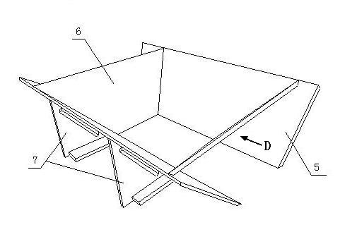
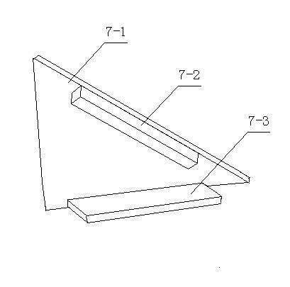
[0029] The wooden formwork structure of the inclined column cap is as follows figure 2 As shown, it is composed of trapezoidal wooden formwork 6 and two column cap rectangular wooden formwork 5, which are respectively inclined 45?? Angle positioning and support. The size and size of two trapezoidal wooden templates 6 are consistent, and the long sides of two rectangular wooden templates 5 can be greater than or equal to the long side dimensions of trapezoidal wooden templates 6, but its short sides are consistent with the height dimensions of rectangular wooden templates 5. The structure of the inclination positioning support member 7 is as image 3, its main body is an isosceles right-angled triangle rib 7-1, along the hypotenuse of the isosceles right-angled triangle, an oblique backing wooden flute 7-2 is installed, and a horizontal backing wooden...

Embodiment 2

[0032] Example 2 The splicing method of the combined wooden formwork of the inclined column cap, the wooden formwork of the horizontal pallet and the wooden formwork of the cylinder

[0033] The splicing steps of the wooden formwork of the inclined column cap combination, the wooden formwork of the horizontal pallet and the wooden formwork of the column are as follows:

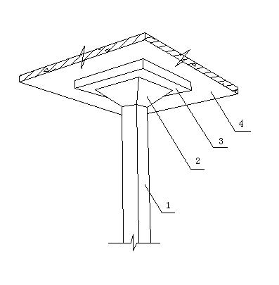
[0034] Such as Figure 10 , the horizontal pallet wooden formwork and column wooden formwork are installed on the scaffold 10 according to the conventional method, the horizontal pallet wooden formwork includes the horizontal pallet bottom formwork 8 and the horizontal pallet side formwork 15, and the center of the horizontal pallet bottom formwork 8 is reserved For the interface to be connected with the wooden formwork of the inclined column cap combination, a space position for installing the wooden formwork of the inclined column cap combination is reserved between the wooden formwork of the column body an...

Embodiment 3

[0037] Example 3 The construction method of the inclined column cap combined with the supporting plate and the column

[0038] The specific construction steps are as follows:

[0039] (1) Install column formwork and floor formwork

[0040] see Figure 10 and Figure 13 , set up the scaffolding 10, and install the column formwork 16, the outside of the column formwork 16 arranges the vertical wooden corrugated 17 and the pull bolt 11 (see Figure 13 ), and at the same time reserve the position for installing the column cap mold and the horizontal pallet mold above the column formwork 16, install the floor formwork corrugated 14 on the reserved position, and install the floor formwork corrugated 14 around the upper part of the reserved position, and install the floor formwork corrugated Install floor template 13 on 14. Floor template 13 reserves the central interface to be installed horizontal pallet wood formwork.

[0041] (2) Install horizontal pallet wood formwork

[00...


PUM


Abstract

The invention relates to an inclination angle column cap combined wood former in a beamless connected upright post, which consists of two trapezoid wood templates and two rectangular wood templates, wherein four peripheries of each trapezoid wood template and upper end surfaces and lower end surfaces of the rectangular wood templates are respectively inclined from the inner side of each plate to the outer side to form a chamfer surface of 45 degrees; the two trapezoid wood templates and the two rectangular wood templates are respectively opposite two by two; each plate is inclined towards theouter side to form an angle of 45 degrees; the two trapezoid wood templates are symmetrically and respectively arranged between the two rectangular wood templates; and two equicrural 45-degree chamfer surfaces are respectively attached to inner side plate surfaces of adjacent rectangular wood template to form an inverted foot pace inclination angle column cap. According to the combined wood former disclosed by the invention, joints between the wood templates as well as between an upper horizontal support plate mould and a lower column body mould are in respectively surface-surface joining relation; a joint between an internal corner and an external corner is compact; the phenomena of concrete mould expansion, mould run and mortar leakage at join parts are avoided; the simpleness in construction is realized; the forming quality of column cap concrete is ensured; the turnover utilization rates of the wood templates are improved; and the construction cost is reduced.

Description

technical field [0001] The present invention relates to the combined wooden mold of the angled column cap without the beam slab and the angled column cap at the top of the supporting plate conjoined column in construction projects such as underground parking garages and large shopping malls, and its splicing with the wooden mold of the horizontal pallet and the wooden mold of the column method. Background technique [0002] In modern housing construction projects, such as large underground parking lots, large shopping malls, logistics centers, office buildings, hospitals and other large-space, long-span, high-clearance buildings use columns with angled column caps and pallets on the top. The top of the column is a column cap that gradually expands upwards, and the top of the column cap is expanded into a horizontal supporting plate, and the top of the horizontal supporting plate is connected to the upper floor, that is, the column, the inclined column cap (that is, the inver...

Claims


Application Information

Patent Timeline
IPC IPC(8): E04G13/02
Inventor 陈克荣薛锋李杰
Owner JIANGSU SHUANGLOU CONSTR GRP
Why Eureka
Try Eureka