Indoor distributed monitoring system for WLAN (Wireless Local Area Network)

A monitoring system and indoor distribution technology, applied in the direction of data exchange details, data switching current sources, electrical components, etc., can solve problems such as no monitoring function, abnormal output power network management center, software crashes, etc., to save maintenance time and save The effect of maintenance costs

Inactive Publication Date: 2012-03-21
珠海银邮光电技术发展股份有限公司
View PDF5 Cites 10 Cited by
  • Summary
  • Abstract
  • Description
  • Claims
  • Application Information

AI Technical Summary

Problems solved by technology

First of all, the AP does not have a complete monitoring function, and can only actively perform simple parameter setting and query on the AP through the AC (WLAN access controller), such as power setting, IP address allocation, data flow query, online query, etc.
The AP cannot detect its own output power, let alone report the AC
In the actual project site, the AP output power is often abnormal but the network management center does not respond, and the fault can only be found in the passive waiting for user complaints or the next inspection
Secondly, after the AP has been used for a period of time, the phenomenon of "hanging" often occurs, that is, the software crashes; after manually going to the site to re-power on, it can work for a while, then hangs again, and then powers on on site, so repeated many times
This phenomenon has occurred on almost all styles of APs. Due to the use of Power over Ethernet switches or Power over Ethernet HUBs, and switches or HUBs do not have automatic reset functions, the phenomenon of "hanging" cannot be cured so far.

Method used


Image

  • Indoor distributed monitoring system for WLAN (Wireless Local Area Network)
  • Indoor distributed monitoring system for WLAN (Wireless Local Area Network)
  • Indoor distributed monitoring system for WLAN (Wireless Local Area Network)

Examples


Embodiment Construction

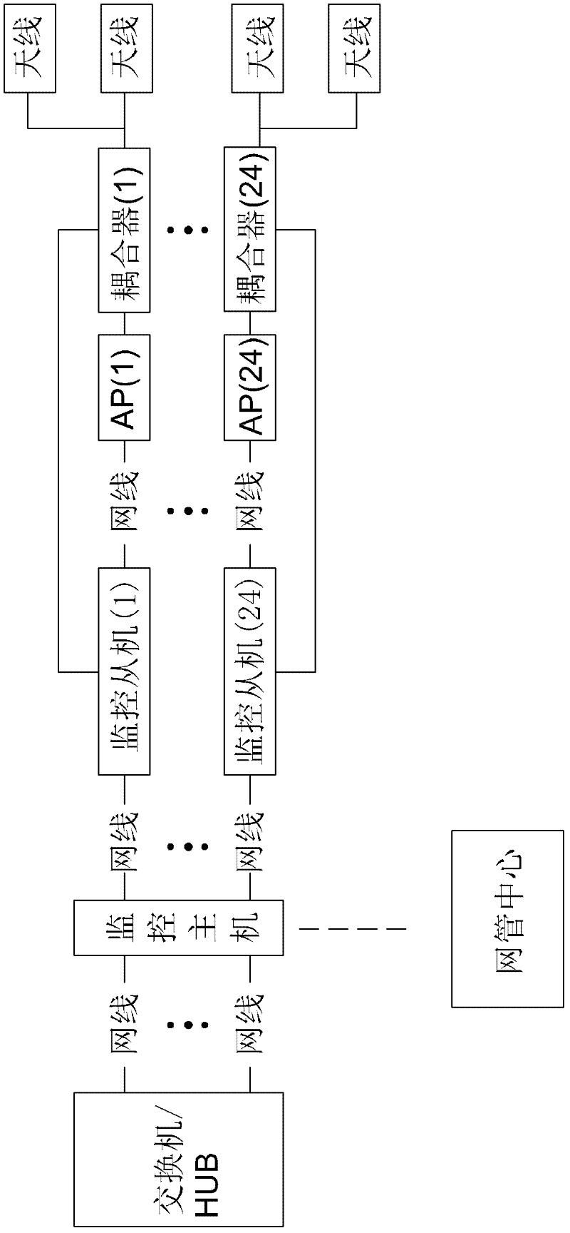
[0026] Such as image 3 , Figure 4 and Figure 5 As shown, the standard output interface for the Ethernet power switch is 24 RJ45 interfaces, a kind of WLAN indoor distribution monitoring system provided by this specific embodiment, it includes a monitoring host, N (N=24) connected with the monitoring host network cable monitoring slave, N (N=24) couplers connected one by one with the monitoring slave and a network management center for wireless communication with the monitoring host, the monitoring host includes N (N=24) first network cable interfaces, N (N=24) second network cable interfaces connected one by one to the first network cable interface, a main MCU module and N (N=24) relays connected to the main MCU module, a first FSK modulation and demodulation circuit, A communication module and an alarm circuit for communication connection with the network management center, a first data line and a first power line are connected between each first network cable interface ...


PUM


Abstract

The invention relates to an indoor distributed monitoring system for a WLAN (Wireless Local Area Network). The monitoring system comprises a monitoring host, N monitoring slaves, N couplers and a network management center (NMC), wherein, the monitoring host comprises N first network cable interfaces, N second network cable interfaces, a main MCU (Microcontroller Unit) module, N relays and a communication module, wherein, first power lines are connected between the first network cable interfaces and the second network cable interfaces, and one relay is serially connected on each first power line; and each monitoring slave comprises a third network cable interface, a fourth network cable interface, an auxiliary MCU module and an Ethernet chip connected with the auxiliary MCU module as well as an AP (access point) radio frequency (RF) power monitoring module, wherein, second data lines are connected between the third network cable interfaces and the fourth network cable interfaces, the Ethernet chips are serially connected on the second data lines, the AP RF power monitoring modules are connected with a coupling output terminal of one coupler, and the N second network cable interfaces are correspondingly connected with the N third network cable interfaces. By adopting the indoor distributed monitoring system, APs can be reset and faults can be located actively so as to save maintenance time and cost.

Description

【Technical field】 [0001] The invention relates to WLAN network monitoring equipment, and to radio frequency technology and embedded technology, in particular to a WLAN indoor distributed monitoring system. 【Background technique】 [0002] Such as figure 1 and figure 2 As shown, WLAN (Wireless Local Area Network, wireless local area network) coverage mainly relies on various types of AP (Access Point, wireless access point) for network construction, and cooperates with the access authentication function of AC (WLAN access controller), The WLAN network system can provide complex services such as data, voice, and monitoring conveniently and quickly for the community. The users in the community use access devices with authentication accounts (that is, WLAN user terminals, such as laptops) to go online anytime and anywhere indoors or outdoors; At present, problems such as network disconnection, slow network speed, and poor roaming in WLAN networks have become increasingly promi...

Claims


Application Information

Patent Timeline
Patent Type & Authority Applications(China)
IPC IPC(8): H04W24/04H04W84/12H04W88/08H04L12/10
Inventor 冯炜余火林
Owner 珠海银邮光电技术发展股份有限公司
Why Eureka
Try Eureka