Method and device for suppressing chattering of work machine

A suppression device and operating machinery technology, applied in the direction of automatic control devices, feeding devices, computer control, etc., can solve the problems of time-consuming and complicated processes, and achieve the effect of immediate performance improvement, simple operation, and rapid processing

Inactive Publication Date: 2012-03-21
NT ENGINEERING CO LTD
View PDF9 Cites 22 Cited by
  • Summary
  • Abstract
  • Description
  • Claims
  • Application Information

AI Technical Summary

Problems solved by technology

Therefore, it is necessary to actually change the rotation speed of the spindle, which not only complicates the process, but also takes time.

Method used


Image

  • Method and device for suppressing chattering of work machine
  • Method and device for suppressing chattering of work machine
  • Method and device for suppressing chattering of work machine

Examples


Embodiment Construction

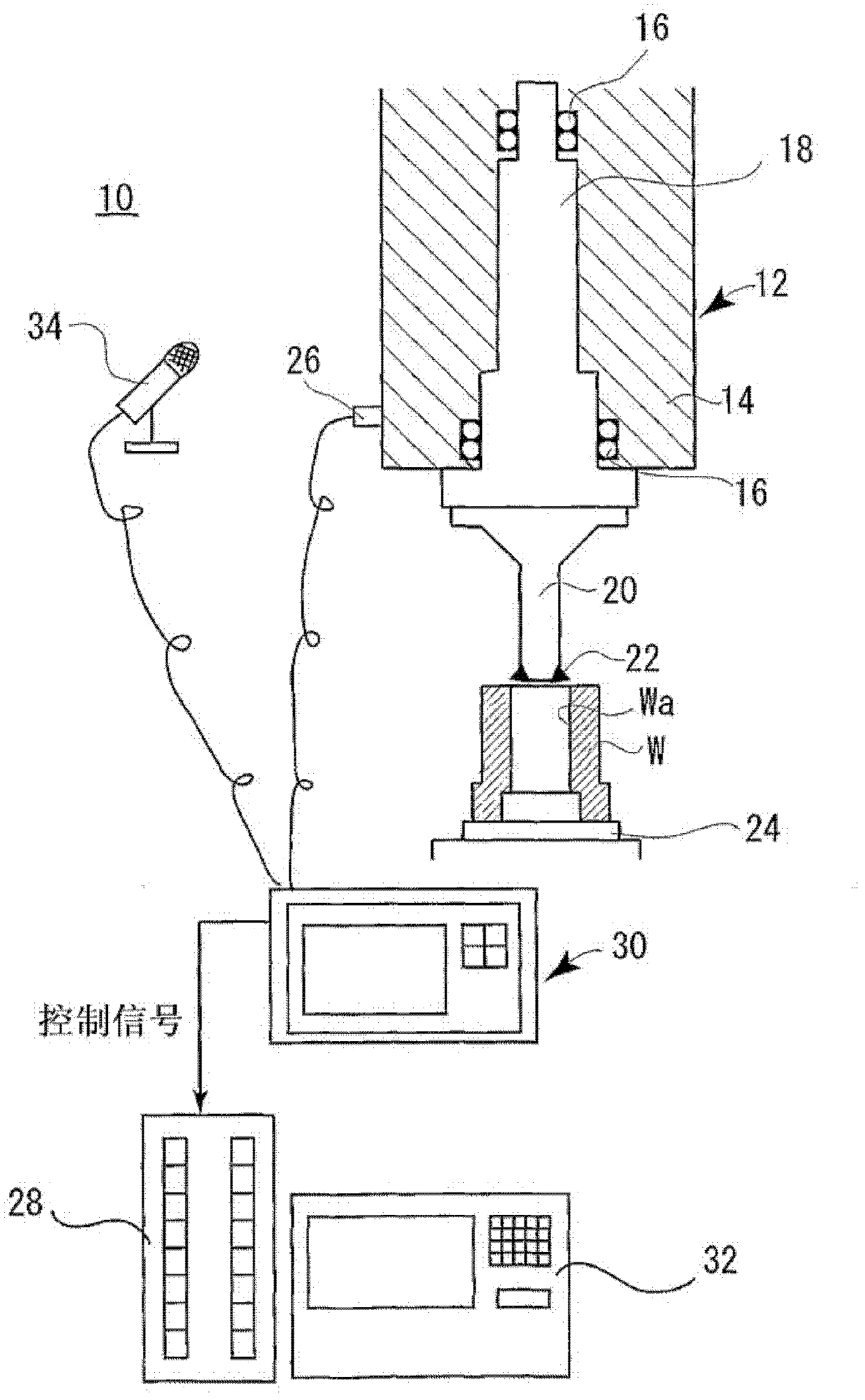
[0028] Such as figure 1 As shown, the chatter suppression device 10 for a working machine according to the first embodiment of the present invention can be applied to a machine tool 12 .

[0029] The machine tool 12 has a rotatable main shaft (spindle) 18 arranged in a casing 14 via a bearing 16, a boring bar (processing tool) 20 detachably attached to the main shaft 18, and a front end of the boring bar 20. Boring cutter 22. A workpiece W is placed on the work table 24 .

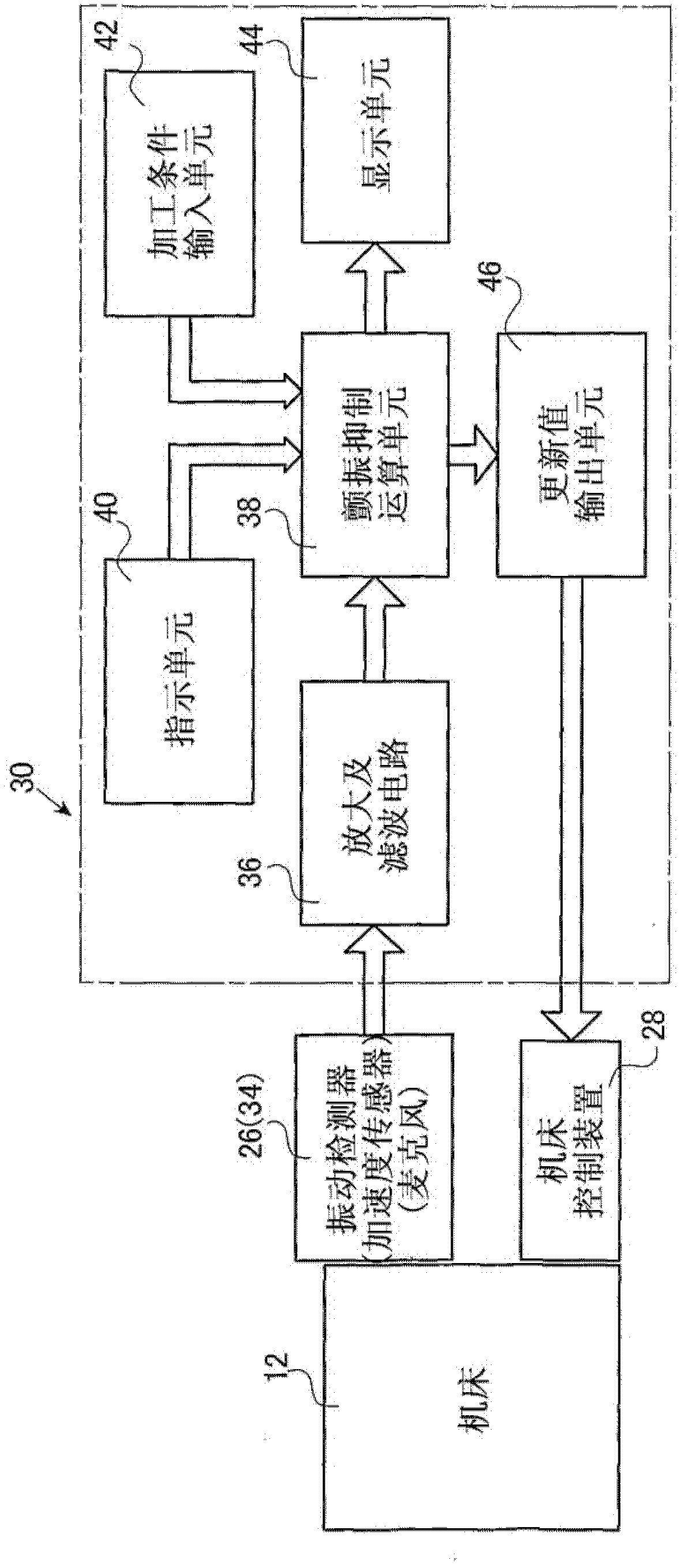
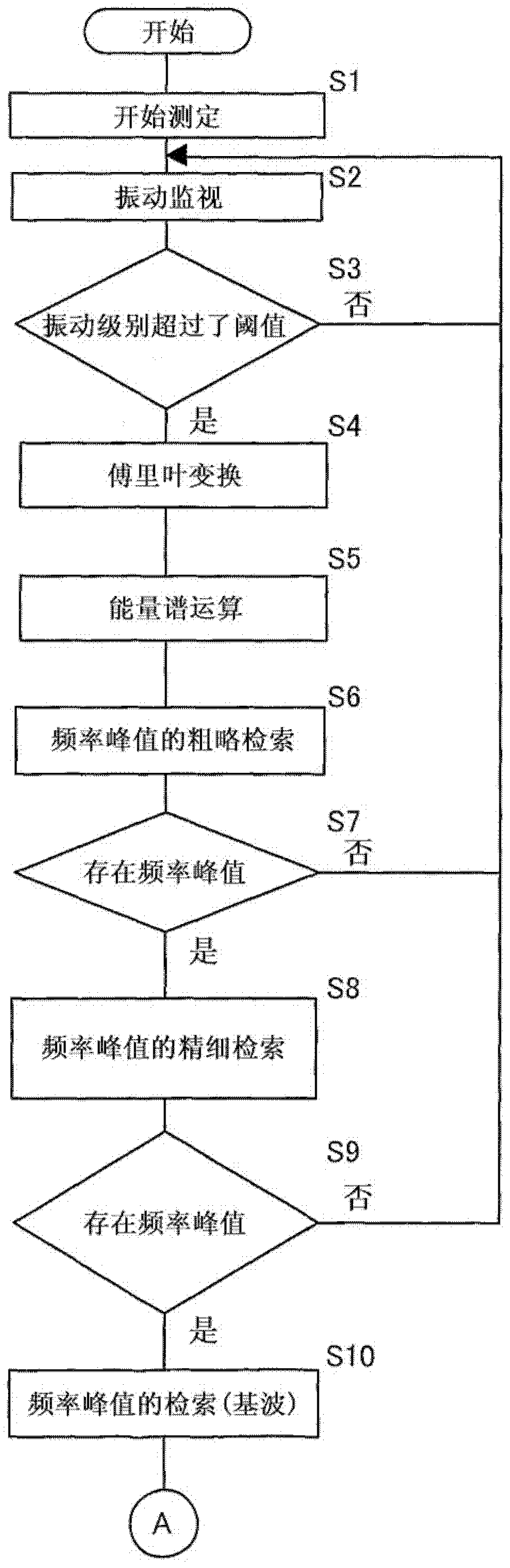
[0030] The chatter suppressing device 10 has an acceleration sensor (vibration detection mechanism) 26 attached to the side of the casing 14 to detect the vibration generated when the boring bar 20 starts to rotate, and analyzes the vibration of the boring bar 20 by Fourier series expansion. The chatter suppression controller 30 that adjusts the rotational speed of the main shaft 18 and outputs an updated value to the machine control device 28 based on the above-mentioned vibration detected when the rotat...


PUM


Abstract

Disclosed is a method for suppressing chattering of a work machine comprising a step (S1) of detecting vibration occurring when the rotation of a bit or a work (W) is started, a step (S3) of determining whether or not the vibration detected after the time when the rotation is started exceeds a threshold, a step (S4) of analyzing the vibration by Fourier series expansion when the vibration is determined to have exceeded the threshold, and a step (S21) of adjusting the rotational speed of the spindle.

Description

technical field [0001] The present invention relates to a method and device for suppressing chatter of an operating machine for suppressing generation of chatter when processing a workpiece with a processing tool. Background technique [0002] In general, various machine tools are used in order to process workpieces by means of processing tools. For example, in boring machining, a boring tool provided with a boring tool (tip) is attached to the rotating spindle (spindle) of a machine tool, and the boring tool is sequentially sent out along the lower hole while rotating at a high speed, thereby A high-precision hole can be machined at a predetermined position according to the machining diameter of the tool nose. [0003] In such work machines, bending due to cutting resistance tends to occur on processing tools and workpieces. Furthermore, the bending may cause vibrations in the machining tool and the workpiece, and the vibrations may appear during machining as chatter vibr...

Claims


Application Information

Patent Timeline
Patent Type & Authority Applications(China)
IPC IPC(8): B23Q15/12B23Q17/12G05B19/404
CPCG05B2219/41115B23Q15/12G05B2219/37434B23Q17/0976G05B2219/34048G05B19/404B23Q17/12
Inventor 山下亨驹井保宏
Owner NT ENGINEERING CO LTD
Why Eureka
Try Eureka