Spindle unit

A technology for spindles and spindle bearings, applied in the direction of large fixed members, maintenance and safety accessories, drive devices, etc., can solve problems such as spindle unit damage

Active Publication Date: 2012-03-28
INDEX WERKE GMBH & CO KG HAHN & TESSKY
View PDF5 Cites 6 Cited by
  • Summary
  • Abstract
  • Description
  • Claims
  • Application Information

AI Technical Summary

Problems solved by technology

[0006] But if the spindle unit is damaged, especially in the area of ​​the spindle motor or one of the spindle bearing units, then the entire spindle unit must be removed from the machine tool and brought to the factory for assembly, because only The spindle unit can be disassembled and reassembled due to high demands on precision
[0007] But this has the disadvantage that it usually takes about a week to remove the spindle unit from the machine tool it is in production and repair the spindle unit

Method used


Image

  • Spindle unit
  • Spindle unit
  • Spindle unit

Examples


Embodiment Construction

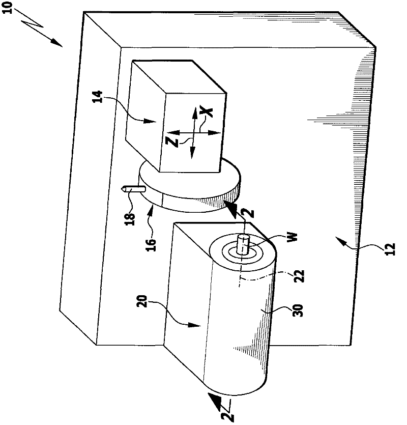
[0055] The machine tool marked with 10 as a whole is in figure 1 The first embodiment shown in includes a frame 12 on which is arranged a tool holder designated as a whole at 14 , which has, for example, a turret head 16 on which a large number of tools 18 can be mounted .

[0056] The turret head 16 is displaceable relative to the machine frame 12 , for example in the direction of the X-axis and in the direction of the Z-axis, in order to be able to process a workpiece W which is mounted rotatably about a spindle axis 22 on a body denoted as a whole by 20 in the spindle unit.

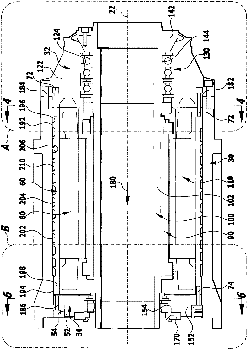
[0057] Such as figure 2 As shown in , the spindle unit 20 comprises a spindle housing 30 which is arranged, for example, firmly or also in a movable manner relative to the frame 12 , but considering the orientation, for example with respect to the X-axis of the machine tool 10 and the Z-axis of the machine tool 10, the spindle housing must be arranged and oriented precisely with reference to the ma...


PUM


Abstract

The present invention provides a spindle unit for a machine tool. The spindle unit comprises a spindle housing and a spindle motor which is equipped in the spindle housing. The spindle motor is provided with a rotor which is configured on the spindle and a stator that is fixed relative to the spindle housing relative to a stator bracket. Furthermore the spindle motor is provided with a front spindle bearing unit and a back spindle bearing unit. The front spindle bearing unit and the back spindle bearing unit support the spindle according to a rotatable mode around an axis of the spindle. For improving the spindle unit and facilitating assembling and maintenance of the spindle unit under a precondition that accuracy requirement is kept, the invention suggests that the front spindle bearing unit and the back spindle bearing unit can be connected to one unit with the stator bracket at an assembling state. The unit comprises the spindle motor and the spindle and furthermore can be placed in the spindle housing as a whole member or detached from the spindle housing. Furthermore at the operation state, at least the front spindle bearing unit can be accurately positioned and fixed relative to the spindle housing through a matching surface.

Description

technical field [0001] The invention relates to a spindle unit for a machine tool, comprising a spindle housing and a spindle motor arranged in the spindle housing, the spindle motor having a rotor arranged on the spindle and relative to the Stator with which the spindle housing is fixed, with a spindle bearing unit at the front, in particular facing the working chamber, and a spindle bearing unit facing away from the working chamber at the rear, which places the spindle so that it can surround the spindle axis Rotational support. Background technique [0002] Such spindle units are known from the prior art. [0003] The spindle unit of a machine tool defines the exact geometric position of the spindle relative to the other machining units in all axes of the machine tool, and therefore, the precision with which workpieces can be manufactured is of paramount importance. [0004] Therefore, in known machine tools, the spindle unit with the spindle motor, the front spindle be...

Claims


Application Information

Patent Timeline
Patent Type & Authority Applications(China)
IPC IPC(8): B23B19/02B23Q11/12
CPCB23Q5/10B23Q1/70
Inventor 冈特·施莱希
Owner INDEX WERKE GMBH & CO KG HAHN & TESSKY
Why Eureka
Try Eureka