
Sonar moving target imaging method based on target echo Doppler characteristics

An echo Doppler and moving target technology, which is applied in the field of sonar imaging based on echo Doppler characteristics, and can solve the problems of high requirements for interpolation filters, high sampling frequency, and large amount of calculation.

Active Publication Date: 2012-03-28
JINZHOU NORTH NAUTICAL INSTR
View PDF2 Cites 23 Cited by
  • Summary
  • Abstract
  • Description
  • Claims
  • Application Information

AI Technical Summary

Problems solved by technology

[0002] The traditional two-dimensional sonar imaging method is time-delay beamforming. This method cannot define the beam in any direction. If you want to define the beam in a certain direction, the required ADC (that is, the analog signal to the digital signal Converter) has a high sampling frequency, requires a large amount of storage, and is difficult to implement in hardware
For the above shortcomings of delay beamforming, high sampling rate can be avoided by interpolation beamforming. If you want to obtain ideal interpolation effect, the requirements for interpolation filter are higher, and the amount of calculation will be huge.

Method used


Image

  • Sonar moving target imaging method based on target echo Doppler characteristics
  • Sonar moving target imaging method based on target echo Doppler characteristics
  • Sonar moving target imaging method based on target echo Doppler characteristics

Examples


Embodiment Construction

[0031] The present invention is described in more detail below in conjunction with accompanying drawing example:

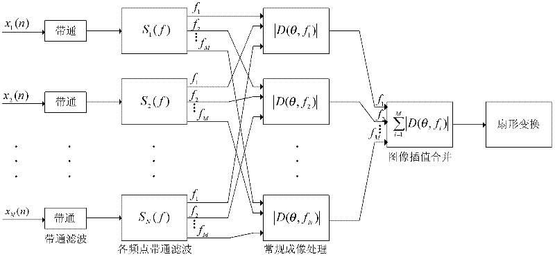
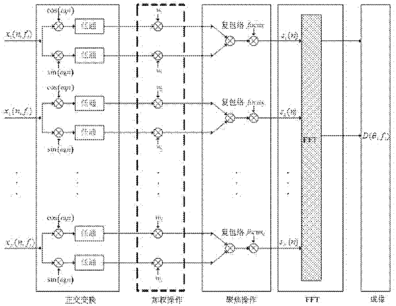
[0032] figure 1 The flow chart of the sonar imaging method based on echo Doppler characteristics is given. The sonar imaging method based on echo Doppler characteristics includes the following steps: (1) band-pass filtering; (2) band-pass filtering at each frequency point; ( 3) Conventional imaging processing of each frequency point; (4) Interpolation and merging; (5) Sector transformation. Depend on figure 2 It can be seen that the conventional imaging process includes the following steps: (1) orthogonal transformation; (2) weighting operation; (3) focusing operation; (4) beamforming operation based on FFT. The echo signals of each element after band-pass sampling and amplitude quantization must first be processed by band-pass filtering. The Doppler frequency shift and the bandwidth of the receiver are determined. For example, when the transmitted signal fre...


PUM


Abstract

The invention provides a sonar moving target imaging method based on target echo Doppler characteristics, which comprises the following steps of: performing band-pass filtering on echo data of each basic element in a receiving basic array; performing band-pass filtering on each frequency point signal to acquire band-pass data of each frequency point; performing quadrature demodulation on the datasubjected to band-pass filtering of each frequency point to acquire an analytic signal form of a real signal; performing Chebyshev weighting and focusing operation on the echo data subjected to quadrature demodulation of each frequency point; acquiring image data of each frequency point in a polar coordinate system by fast Fourier transform (FFT) beam forming; and performing interpolation mergingon the image data subjected to FFT beam forming of each frequency point, and converting an image in the polar coordinate system into an image which accords with the visual habit of people in a rectangular coordinate system by sector conversion. By the FFT beam forming, the method can be implemented by an FFT algorithm in digital signal processing, and the requirement of system real-time imaging is met.

Description

technical field [0001] The invention relates to a sonar imaging method, in particular to a sonar imaging method based on echo Doppler characteristics. Background technique [0002] The traditional two-dimensional sonar imaging method is time-delay beamforming. This method cannot define the beam in any direction. If you want to define the beam in a certain direction, the required ADC (that is, the analog signal to the digital signal Converter) has a high sampling frequency, requires a large amount of storage, and is difficult to implement in hardware. For the above shortcomings of delay beamforming, interpolation beamforming can be used to avoid high sampling rates. If you want to obtain ideal interpolation effects, the requirements for interpolation filters are relatively high, and the amount of calculation will be large. Contents of the invention [0003] The purpose of the present invention is to provide a sonar moving target imaging method based on target echo Doppler ...

Claims


Application Information

Patent Timeline
Patent Type & Authority Applications(China)
IPC IPC(8): G01S15/89G01S7/537
Inventor 孙大军张友文张殿伦滕婷婷勇俊刘鑫师俊杰
Owner JINZHOU NORTH NAUTICAL INSTR
Learn More