LED (light-emitting diode) lamp panel adopting COB (Chip On Board) technology

A technology of LED lamp board and process, which is applied in the direction of electric lamp circuit layout, lighting device, light source, etc.

Inactive Publication Date: 2012-03-28
SHANGHAI LEADESCO LIGHTING TECH CO LTD
View PDF7 Cites 6 Cited by
  • Summary
  • Abstract
  • Description
  • Claims
  • Application Information

AI Technical Summary

Problems solved by technology

[0005] The technical problem to be solved by the present invention is to provide an LED light board using COB technology, which is suitable for high-demand use environments and large-area applications, thereby overcoming the shortcomings of existing LED light boards

Method used


Image

  • LED (light-emitting diode) lamp panel adopting COB (Chip On Board) technology
  • LED (light-emitting diode) lamp panel adopting COB (Chip On Board) technology
  • LED (light-emitting diode) lamp panel adopting COB (Chip On Board) technology

Examples


Embodiment Construction

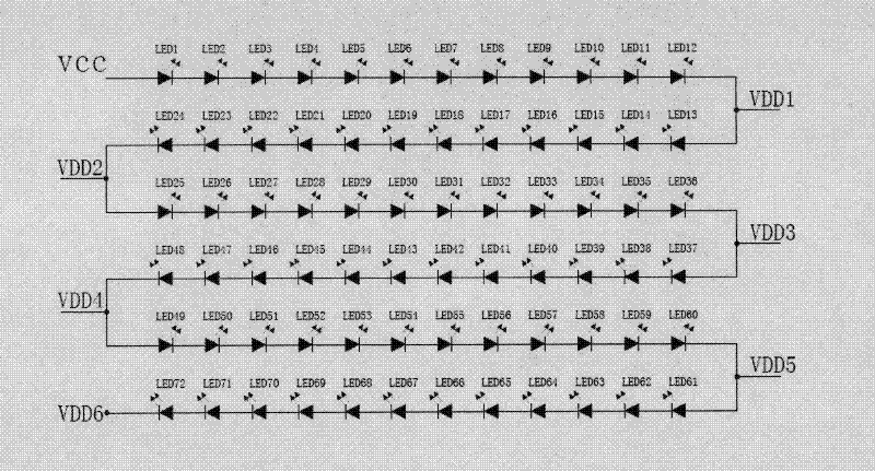
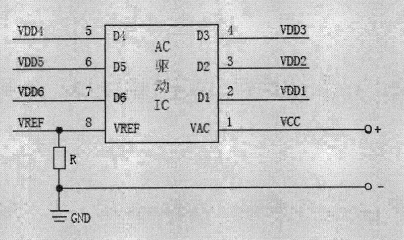
[0017] The present invention is an LED light board adopting COB technology, including a substrate, LED bare chips and AC drive chip bare chips packaged on the substrate by COB technology, please refer to figure 1 , figure 2 As shown, the AC drive chip die is connected to the LED die through a circuit.

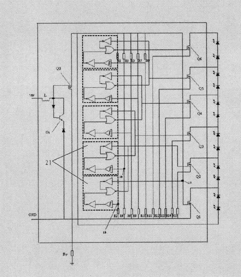
[0018] Please refer to image 3 As shown, the AC drive chip used in the present invention mainly includes a voltage input module, a voltage distribution module, multiple sets of buffer-voltage comparison modules 21 and semiconductor field effect transistors MOSFET Q1-Qn.

[0019] Wherein, the semiconductor field effect transistors MOSFETs Q1-Qn can be V-groove field effect transistors VMOS. The source of MOSFET Q1 is connected to the ground potential, the gate is directly connected to one input terminal of the first group of buffer-voltage comparison modules, and simultaneously connected to the output terminal of the voltage input module, and the other input terminal of the ...


PUM


Abstract

The invention relates to an LED (light-emitting diode) lamp panel adopting COB (Chip On Board) technology, comprising a base plate, and an LED bare chip and an alternating current driving bare chip packaged on the base plate by the COB technology, wherein the alternating current driving bare chip and the LED bare chip are connected with each other by a circuit. In the LED lamp panel, as the LED chip and a drive IC (integrated circuit) chip are bonded on the base plate simultaneously, the defects of the existing LED COB lamp panel are remedied, the power factor is above 0.95, the total harmonic distortion is no more than 20%, and the electromagnetic compatibility satisfies the international standards of EN55015, EN61547 and the like, so that the LED lamp panel is applicable to various using environments with high requirements and large-area application.

Description

technical field [0001] The invention relates to the field of LED lighting appliances, in particular to an LED lamp board adopting a COB (Chip on Board, chip bonded on a substrate) process. Background technique [0002] COB is the most widely used packaging process for LED light boards. However, due to the large number of parts and large volume of the existing light board driving components, most of them are designed as independently installed components. Therefore, usually only the bare LED The chip (LED Chip) is bonded on the substrate, and the driving part is completely separated from the light board, so they cannot be bonded together by the COB process. [0003] The above-mentioned existing LED COB light boards all work in a low-voltage state (working voltage ranges from a few volts to more than ten volts). Although they can meet the basic requirements of LED light-emitting components, their technical indicators, such as power factor, harmonics and EMC (Electromagnetic C...

Claims


Application Information

Patent Timeline
Patent Type & Authority Applications(China)
IPC IPC(8): H05B37/02
Inventor 张高柏陈卫平
Owner SHANGHAI LEADESCO LIGHTING TECH CO LTD
Why Eureka
Try Eureka