Welding head for rail welding

A welding head and guide rail technology, applied in welding equipment, rails, rails, etc., can solve problems such as expensive, train derailment, cracks, etc.

Active Publication Date: 2012-03-28
达维德瓦亚
View PDF2 Cites 6 Cited by
  • Summary
  • Abstract
  • Description
  • Claims
  • Application Information

AI Technical Summary

Problems solved by technology

But this process has a serious disadvantage: Since the metal is still in a plastic state and is under heavy tension when the end of the rail is released by the retracted clamping element for the half-head, these tensions can lead to changes in the newly welded joint, thereby lead to the formation of e.g. cracks
The process

Method used


Image

  • Welding head for rail welding
  • Welding head for rail welding
  • Welding head for rail welding

Examples


Embodiment Construction

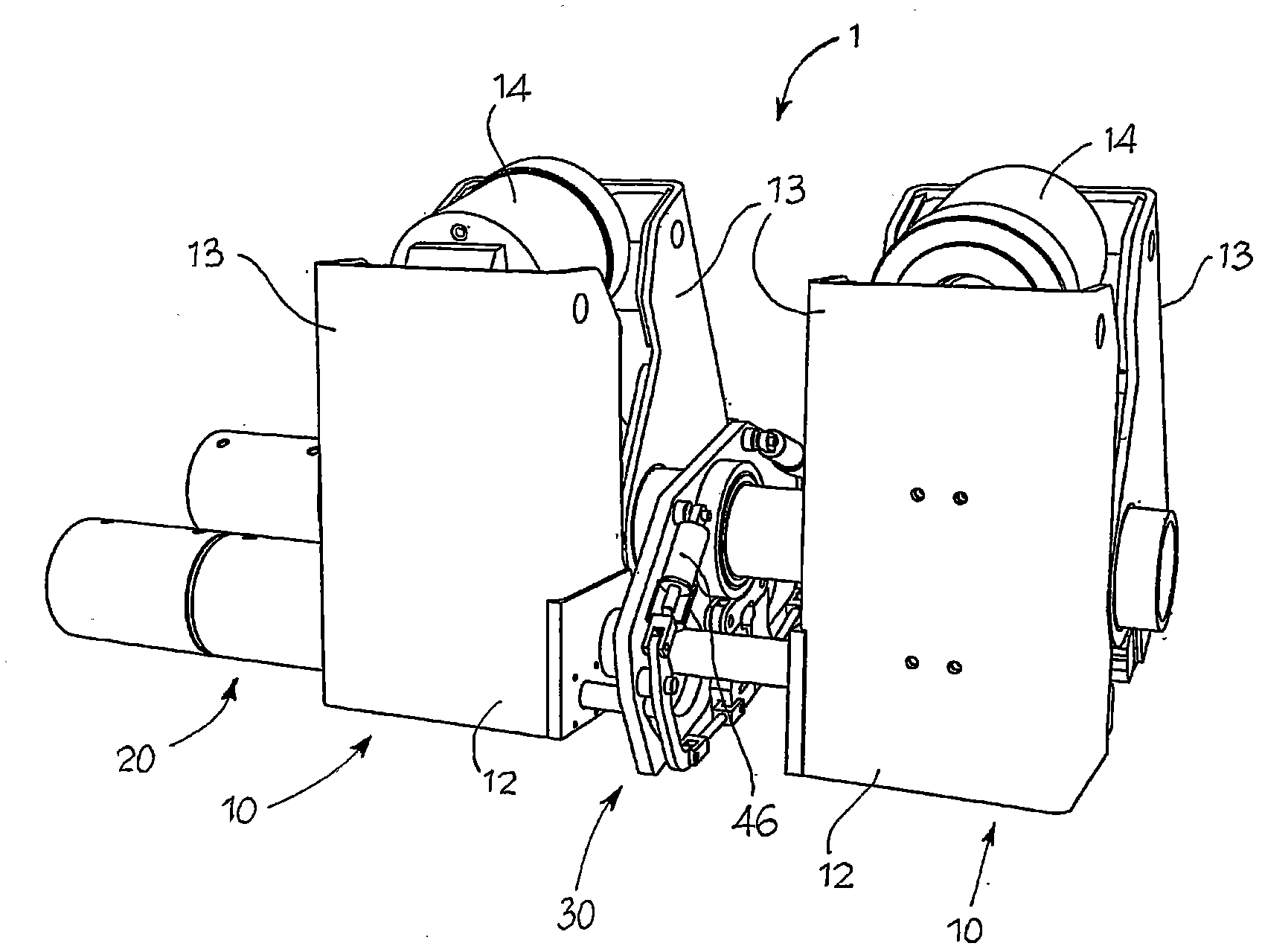
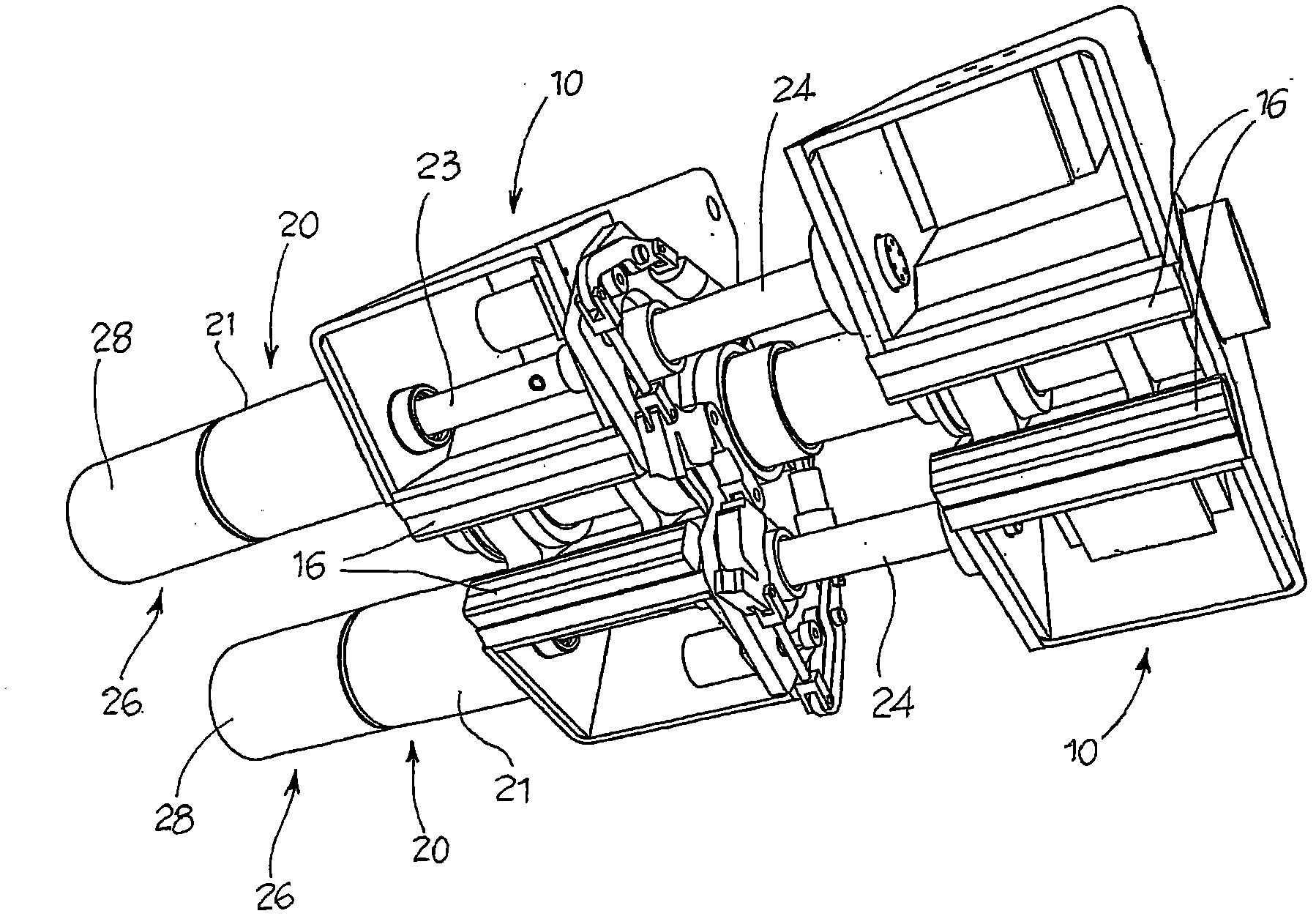
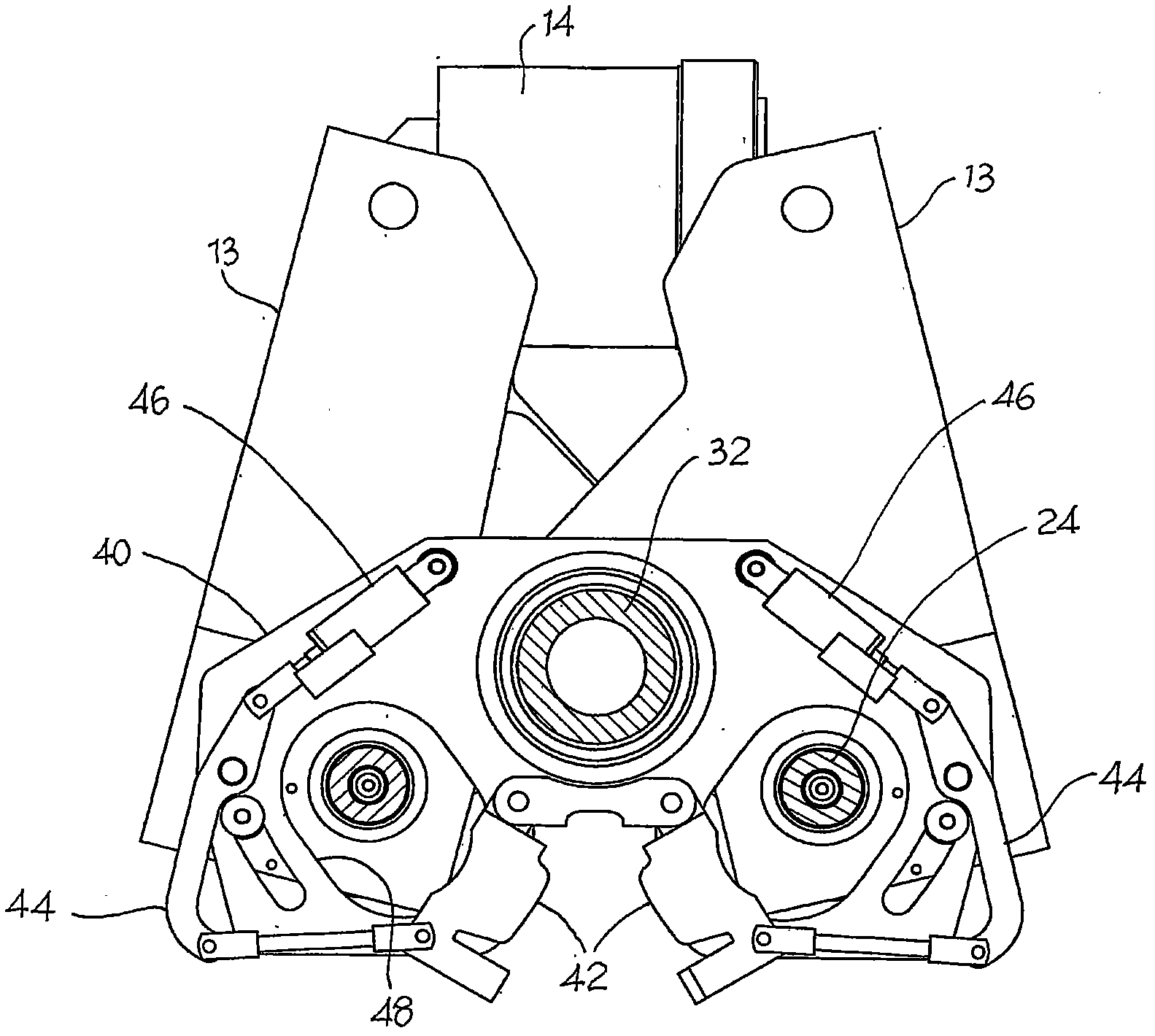
[0035] Referring to the drawings, reference numeral 1 generally designates a welding head for welding the ends of two sections or sections of a rail according to the invention. The welding head 1 comprises two head halves 10 aligned and sliding relative to each other along the longitudinal direction X. Each head half 10 includes gripping means 12 to grip the corresponding section of the rail. Said clamping device 12 comprises, for example, a clamping element produced by two lever members 13 controlled to open and close to grip the profile of the rail segment by means of an actuator mechanism 14 such as Realized by the hydraulic jack of the clamp.

[0036] The welding head also comprises an electric welding circuit comprising at least two electrodes 16 adapted to come into contact with the respective rail profile so as to create an electrical short circuit between the ends of the two sections of the rail so that A flash-butt welding process is performed; this process will res...


PUM


Abstract

This invention concerns a welding head for welding the extremities of two sections of rail and comprises two half -heads (10) aligned and sliding with regard to one another in a longitudinal direction. Each half -head comprises grip means (12, 13) to grasp a respective section of rail and two electrodes (16) suitable for contact with respective sections of rail in order to carry out a flash butt weld. The head also comprises traction actuator means (20) which extend in a longitudinal direction and are connected to the two half- heads (10) to shift the two half-headsin a longitudinal direction one towards the other, said traction actuator means (20) having a stroke suitable for allowing, during a cycle of welding two sections of rail, simultaneous regulation of rail tensions.

Description

technical field [0001] The invention relates to a welding head for rail welding by means of a flash butt welding or induction welding process. Background technique [0002] Welding heads of known type generally comprise two aligned sliding halves that can be moved by means of one or more hydraulic traction jacks. Each half-head usually consists of a frame with clamping elements, such as two lever parts, which can be activated by means of their own hydraulic jacks to grasp the two rails to be welded together the corresponding end of one of them. Furthermore, the half-heads are equipped with suitable electrodes for applying the welding current at the end of the rail. [0003] During welding, the two rail ends are heated to their melting point due to the high induction caused by the electric current, and after the initial preheating phase, the two ends are pressed together so that the so-called upsetting or forging of the joint area is not the same as the two Continuous prog...

Claims


Application Information

Patent Timeline
IPC IPC(8): B23K11/00
CPCB23K2201/26B23K11/046E01B29/46B23K2101/26B23K11/00B23K11/36
Inventor 达维德·瓦亚
Owner 达维德瓦亚
Why Eureka
Try Eureka