

Moisture resistant coatings for polymeric enclosures
一种聚合物、耐湿性的技术,应用在照明装置的零部件、照明装置、信号装置等方向,能够解决灯性能影响等问题
- Summary
- Abstract
- Description
- Claims
- Application Information
AI Technical Summary
Problems solved by technology
Method used
Image

Examples
Embodiment 1
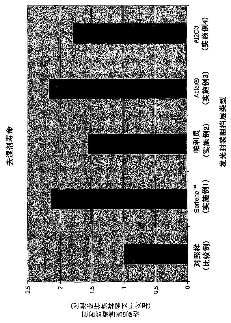
[0053] The inner surface of the polycarbonate test panel was roughened and dip-coated on both sides with a PVDC copolymer emulsion (Serfene TM 2022, Rohm & Haas Company). The calculated moisture permeability coefficient of PUDC copolymer is about 7.80E - 12 (cm2 / s-Pa). The moisture permeability coefficient of polycarbonate substrate is 1.05E - 10 (cm2 / s-Pa). The panels were allowed to dry at room temperature to form a moisture barrier. The thickness of this layer is 5-30 mils. Then connect the test board to the light-emitting package for the desiccant lifetime test. image 3 This moisture barrier was shown to increase desiccant lifetime by a factor of 2.1.
Embodiment 2
[0055] The inside surfaces of the polycarbonate test panels were coated with the barrier material Parylene C (Specialty Coating Systems Inc) by vapor deposition. The moisture permeability coefficient of Parylene C is 5.2080E - 12 (cm2 / s-Pa). The thickness of the barrier layer is about 25 microns. Connect the test board to the light-emitting package to perform the desiccant lifetime test. image 3 This moisture barrier was shown to increase desiccant lifetime by a factor of 1.6.
Embodiment 3
[0057] Using a double-sided silicone adhesive, apply 4 mil thick Aclar (Honeywell International Inc) film was bonded to the inside surface of a polycarbonate test panel. Aclar The moisture permeability coefficient of Wei 1.6E - 13 (cm2 / s-Pa). Connect the test board to the light-emitting package to perform the desiccant lifetime test. image 3 This moisture barrier was shown to increase desiccant lifetime by a factor of 2.2.
PUM
 Abstract
Description
Claims
Application Information